
Black enhancement in perceptual gamut mapping

Active Publication Date: 2007-10-11
CANON KK +1
View PDF8 Cites 11 Cited by
  • Summary
  • Abstract
  • Description
  • Claims
  • Application Information

AI Technical Summary

Benefits of technology

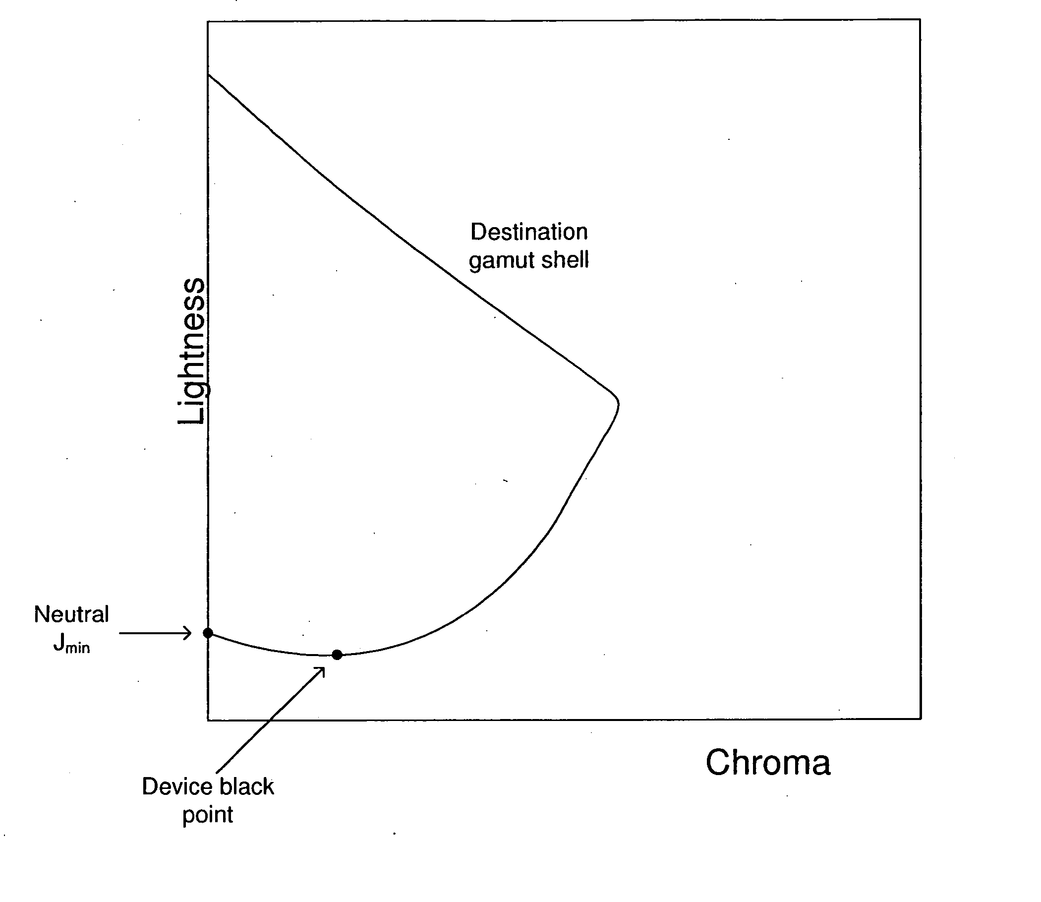
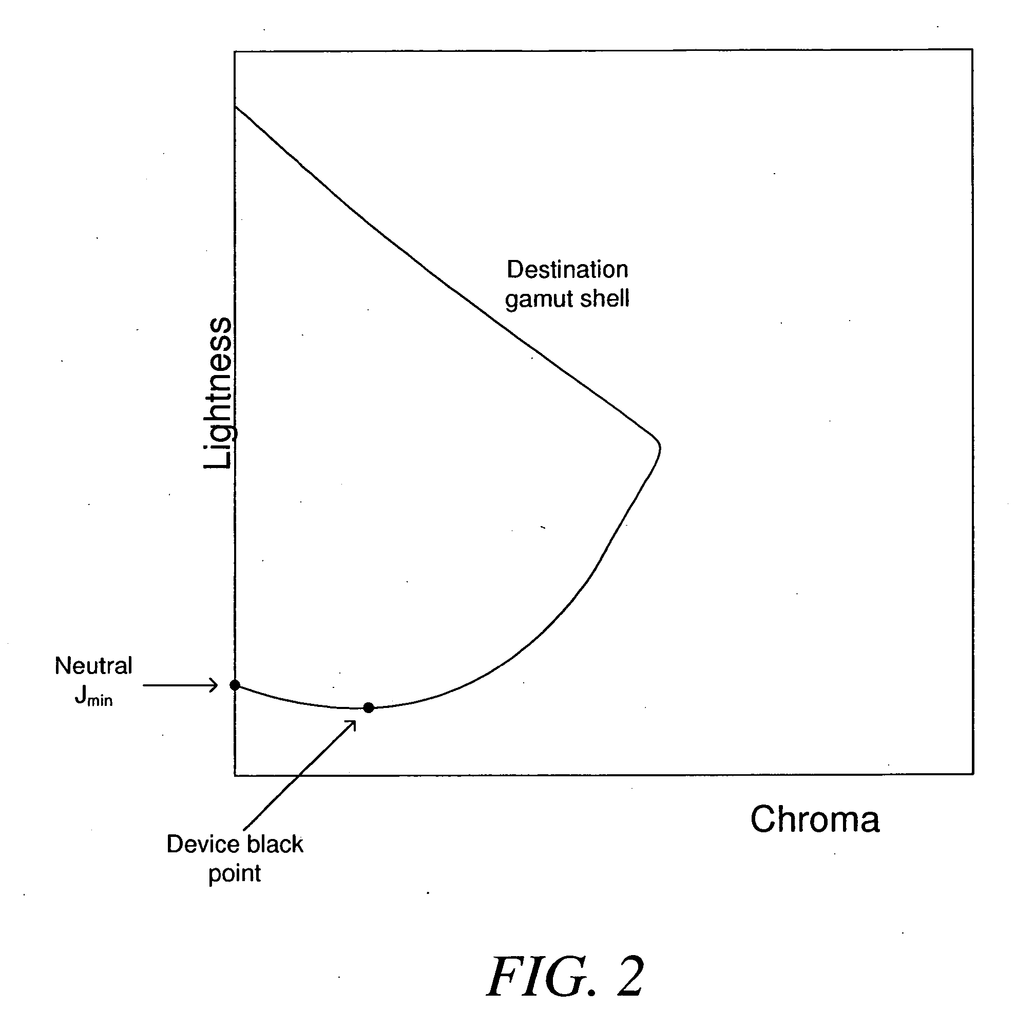
[0012] In view of the foregoing, the present invention provides for gamut mapping between a source device and destination device, which are respectively characterized by a source gamut shell and a destination gamut shell. A lightness compression using the destination device black point instead of the neutral minimum lightness is first performed. Then, a constant lightness transformation is performed which modifies the destination gamut shell so that a shell boundary thereof on a hue plane containing the destination device black point is shifted from an original position to align with a neutral axis of the destination gamut shell. Chroma compression is performed. An inverse constant lightness transformation is performed, wherein the inverse constant lightness transformation returns the shell boundary to the original position. As such, dark, near-neutral colors can be reproduced with increased and / or maximum density on the destination device, resulting in improved depth and increased contrast.

Problems solved by technology

However, use of the neutral maximum and minimum lightnesses for initializing lightness scalers is not without problems.
However, this color does not usually correspond with the neutral minimum lightness in the color appearance space of the printer.
Furthermore, in a case of reproducing images from a monitor to a printer, the monitor black (i.e., R=G=B=0) will likely not be printed with the highest density possible by the printer.
It is therefore likely that the image quality of the printer will lack depth and contrast when printing dark, almost neutral colors.

Method used


Image

  • Black enhancement in perceptual gamut mapping
  • Black enhancement in perceptual gamut mapping
  • Black enhancement in perceptual gamut mapping

Examples


Embodiment Construction

[0027] Referring to FIG. 3, a diagram that provides a general explanation of a color management process in which a color management module uses a gamut mapping algorithm, in accordance with an exemplary embodiment of the invention, is shown. As seen in FIG. 3, color management module 302 includes a gamut mapping algorithm which accesses source and destination gamut shells 306 corresponding to a source device and a destination device. The source device generates source color image data 300, and the destination device produces color image data 304 which corresponds to the generated source color image data 300.

[0028] Lightness compression and chroma compression are performed in the gamut mapping algorithm. Between lightness compression and chroma compression, a constant lightness transformation is performed to the effect that the destination gamut shell is modified so that a shell boundary of the destination gamut shell on a hue plane containing the device black point of the destinati...


PUM


Abstract

The present invention provides for gamut mapping between a source device and a destination device, the destination device having a destination device black point with a hue, and the source device and the destination device being respectively characterized by a source gamut shell and a destination gamut shell. A lightness compression is performed using the source gamut shell, the destination gamut shell and the destination device black point. A constant lightness transformation is performed, wherein the constant lightness transformation modifies the destination gamut shell so that a shell boundary of the destination gamut shell on the hue plane containing the destination device black point is shifted from an original position to align with a neutral axis of the destination gamut shell. A chroma compression is performed using the source gamut shell and the modified destination gamut shell. An inverse constant lightness transformation is performed to obtain mapped colors for the destination device, wherein the inverse constant lightness transformation returns the shell boundary to the original position. As such, dark, almost neutral colors can be produced with virtually the highest possible density for the destination device.

Description

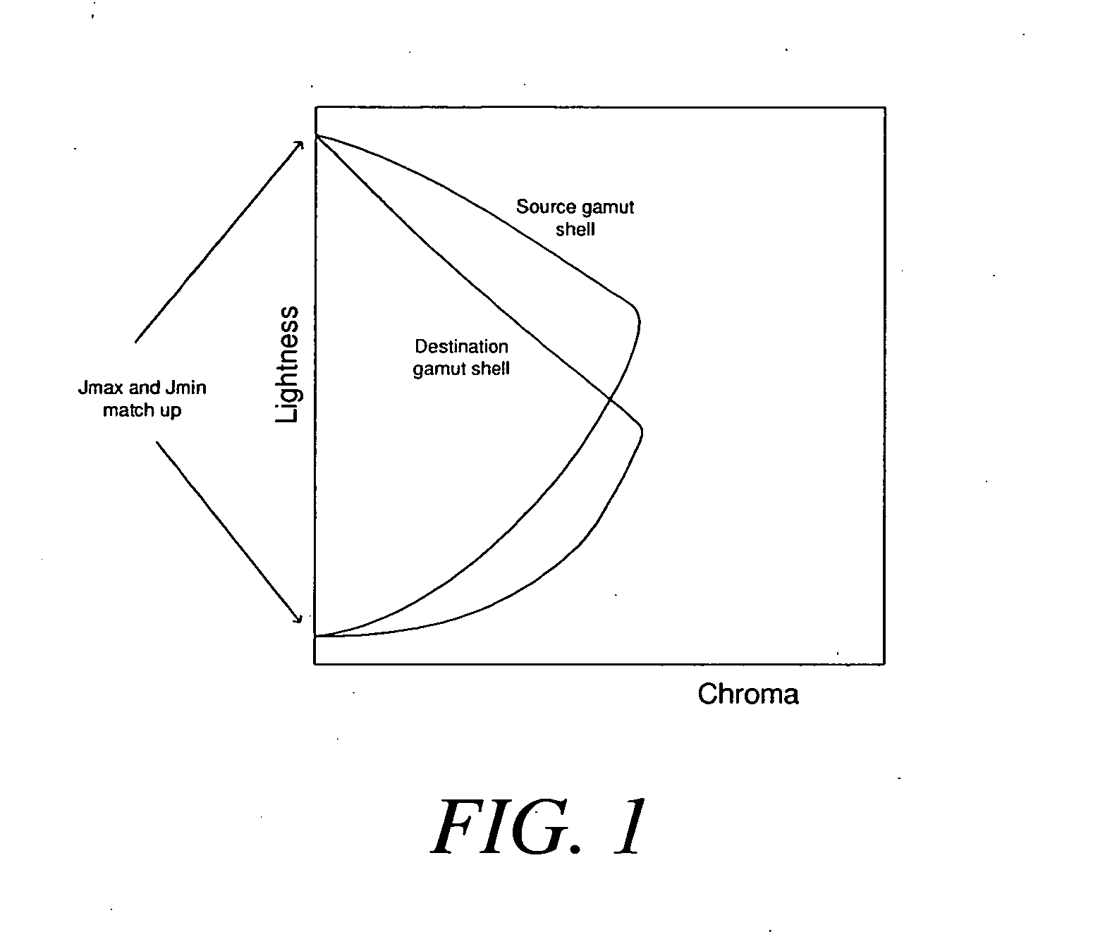
BACKGROUND OF THE INVENTION [0001] 1. Field Of The Invention [0002] The invention relates to the field of gamut mapping for color devices, and more particularly relates to gamut mapping between a source device and a destination device, the destination device having a destination device black point with a hue, and the source and destination devices being respectively characterized by a source gamut shell and a destination gamut shell. [0003] 2. Description Of The Related Art [0004] Gamut mapping is used to reproduce an image rendered by a source device on a destination device, since the source device and the destination device typically have different gamut boundaries with respect to each other. In other words, the gamut of colors that can be reproduced by the source device is typically not the same as the gamut of colors that can be reproduced by the destination device. Gamut mapping can be used to render the image from within the source device gamut boundary to within the destinati...

Claims


Application Information

Patent Timeline
IPC IPC(8): G09G5/02
CPCH04N1/6058
Inventor TIN, SIU-KEI
Owner CANON KK
Learn More