
Method for improving the depth of field and resolution of microscopy

Inactive Publication Date: 2005-07-28
CHIANG ANN SHYN
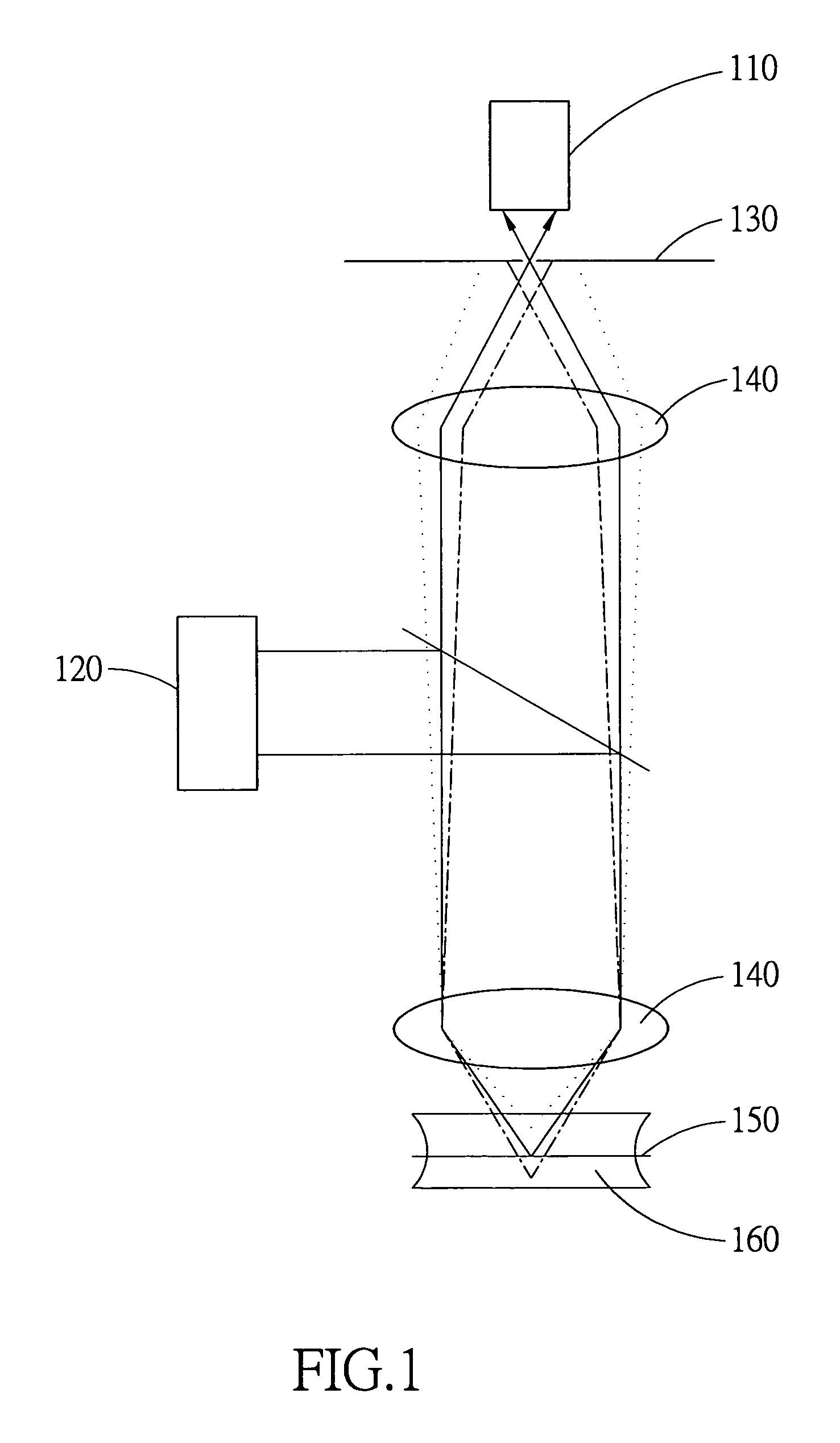
View PDF7 Cites 19 Cited by
  • Summary
  • Abstract
  • Description
  • Claims
  • Application Information

AI Technical Summary

Benefits of technology

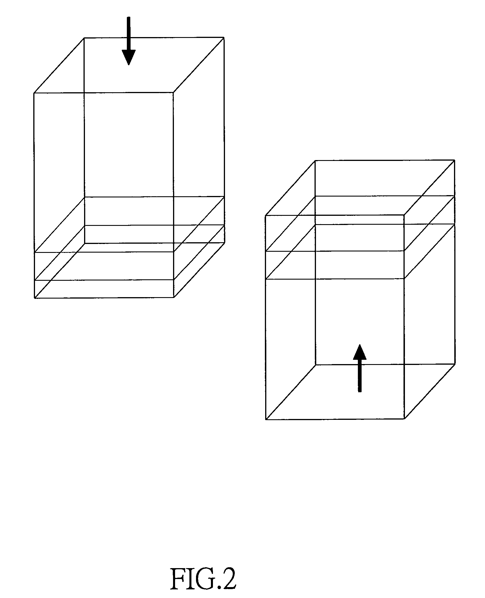
[0008] In accordance with the present invention, a method for improving the depth of field and resolution of microscopy is provided. According to this invention, the 3D image of a sample with deeper thickness can be obtained by performing the obverse and the opposite scan to the sample.
[0009] It is another object of this invention to provide a method for improving the depth of field and resolution of microscopy. The method of this present invention can improve the depth of field and resolution by combining the obverse and the opposite scanning images of a sample.
[0010] It is still another object of this invention to provide a method for improving the depth of field and resolution of microscopy. According to the above-mentioned design, the preparation before performing microscopic scanning can be simplified by reducing the number of cut pieces of the observed sample.
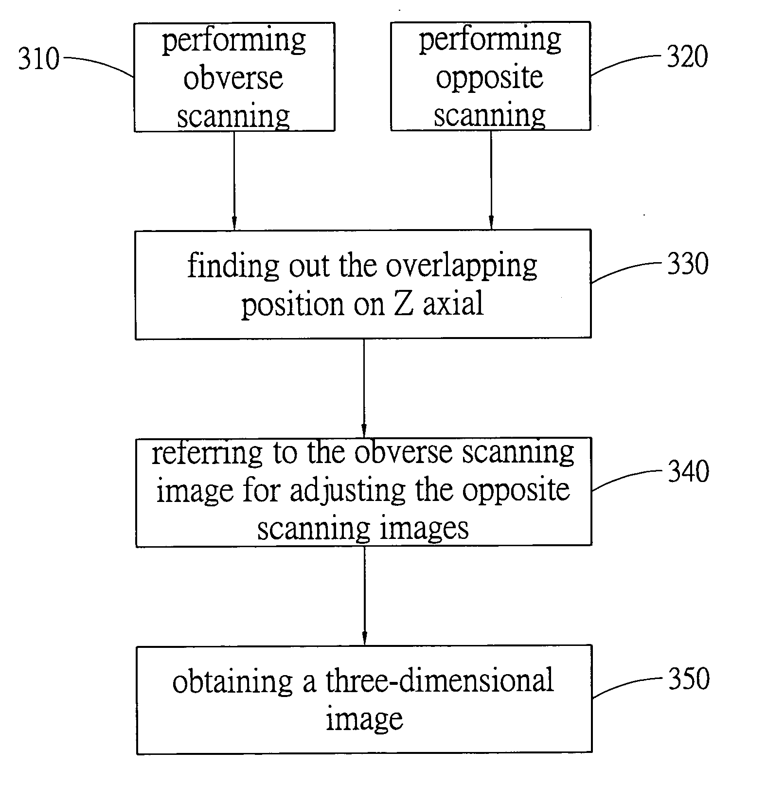
[0011] In accordance with the above-mentioned objects, the invention provides a method for improving the depth of field and resolution of microscopy. The above-mentioned method at least comprises the following steps: fixing a sample in three-dimensional space with embedding gel, performing the obverse scanning and the opposite scanning to the sample, finding out the overlapping position of the obverse and the opposite scanning images on Z axial, using the image of the overlapping area on Z axial to adjust the opposite scanning images, wherein the adjustment is referred to the obverse scanning images, and combining the obverse and the opposite scanning images to obtain a complete three-dimensional image. According to this invention, the depth of field can be increased, and thus the resolution of the microscopic image can be improved. Moreover, the thickness of the three-dimensional image obtained by the above-mentioned design is thicker than the image obtained by the method in the prior art. More preferably, the sample can be cut into fewer pieces for performing the microscopic scanning of this invention. That is, according to the above-mentioned design, the preparing procedures before performing microscopic scanning is more easier than that in the prior art.

Problems solved by technology

In traditional microscope, when observing the image of a thick organism in Z coordination, the research is limited to the focus range of the depth of field of the object lens used therein.
If the size of the observed target were over the range, the light of the focus plane would be seriously interfered with the light out of the focus plane.
Thus, the contrast of the obtained image is decreased, and the obtained image becomes blurred.
However, the above-mentioned design will increase the cost of the hardware very much.
Of course, the second way will also increase the hard ware cost.

Method used


Image

  • Method for improving the depth of field and resolution of microscopy
  • Method for improving the depth of field and resolution of microscopy
  • Method for improving the depth of field and resolution of microscopy

Examples


first embodiment

[0042]FIG. 9 shows the surface spectrums of the obverse and the opposite scanning images. Picking the lowest of the obverse scanning images and every of the opposite scanning images, the rough position of the lowest of the obverse scanning images relative to the opposite scanning images on Z axial can be determined by using fast Fourier Transferring to calculate the peaks during rotating the two images, as shown in FIG. 7. Then, by the mentioned Sobel edge checking concept, the portion with larger edge variation, such as the rectangle flame with bold lines in FIG. 5C, can be found out. Using the above-mentioned portion and the relative matching method, the image in the opposite scanning images most similar to the image A in the obverse scanning images can be found, and the overlapping position of the obverse and the opposite scanning images on Z axial can be determined. The flow chart for determining the overlapping position on Z axial is shown as FIG. 8. After determining the overl...

second embodiment

[0043] The thickness of the cerebrum of a fly is about 160 μm. After marking the cranial nerve cells with green fluorescence protein and activating with a 488 nm laser, the complete three-dimensional image of the cerebrum can be taken. However, it is found that when the depth of the sample is deeper, the taken image by the laser becomes more blurred. That is cause by the light-absorption of the organism sample. The energy of the activated light or the emitted light is absorbed by the sample, and thus the taken three-dimensional image becomes very blurred under some depth. When employing the method of this invention, in order to obtain a complete and clear three-dimensional cerebrum image, it is only required to scan to a little deeper than the depth of the cerebrum for the obverse and the opposite scanning, and to combine the obtained images.

third embodiment

[0044] Generally, in order to perform a confocal microscopic scanning, an organism tissue thin slice may be buried in glycerol for microscopic scanning and the following recording. By cooperating with the method of this invention, the thickness of the target organism tissue sample can be raised to about twice than the thickness of the organism tissue sample in the prior art. After embedding an organism tissue sample with sample embedding gel for fixing it in three-dimensional space, a complete and clear 3D organism image can be obtained by scanning the sample until the scanning depth a little deeper than the thickness of the sample for taking the obverse and the opposite scanning images and combining the above-mentioned scanning images. The thickness of the three-dimensional image obtained by the above-mentioned method is twice as thick as the thickness obtained by the sample buried in glycerol and scanned by the prior art method.


PUM


Abstract

This invention is about a microscopic technology for improving depth of field and resolution by obverse and opposite scanning and 3D image combination. According to the above-mentioned design, the thickness of the three-dimensional image can be increased, and the image resolution and the depth of field can be improved. After fixing a sample in 3D space with embedding gel, the obverse and opposite scanning are performed to the sample, and the images obtained from the mentioned scanning are combined to achieve the 3D microscopic image with the deeper depth of field. The mentioned 3D image combination comprises the application of fast Fourier Transferring, Sobel edge checking, and relative matching to determine the overlapping position of the obverse and the opposite scanning images on Z axial. After finding out the shift on X Y plane and the rotation pivoted with Z axial by fast Fourier Transferring theory, the upper and the lower images are adjusted, and a complete 3D image is achieved.

Description

BACKGROUND OF THE INVENTION [0001] 1. Field of the Invention [0002] This present invention relates to a method of microscopy, and more particularly, to a method for improving the depth of field and resolution of microscopy by performing the obverse and opposite scanning and combining the images. [0003] 2. Description of the Prior Art [0004] Confocal microscopy in the prior art can achieve high-resolution microscopic image of sample in different depth by removing the noise from non-focus plane. The above-mentioned method comprises the following steps. First, a laser is focused to a single radiant with an object lens, and the radiant is employed to irradiate to a specific depth of a sample. Then, the light reflected or dispersed from the focus radiant can be focused to a single beam by the same object lens, and completely pass through the pinhole aperture in front of an image detector. Finally, the other photons, above or bellow the focus, are blocked by the surroundings of the mentio...

Claims


Application Information

Patent Timeline
IPC IPC(8): G02B21/00G06K9/40
CPCG02B21/006G02B21/008G02B21/0072
Inventor CHIANG, ANN-SHYN
Owner CHIANG ANN SHYN
Learn More