Extruder mid-barrel adjustable valve assembly

a technology of adjustable valves and extruders, which is applied in the direction of clay mixing apparatuses, rotary stirring mixers, mixers with horizontally mounted tools, etc., can solve the problems of unsanitary, unadjustable devices, and increased back pressure and shear

Inactive Publication Date: 2007-10-11
WENGER MANUFACTURING INC
View PDF16 Cites 29 Cited by
  • Summary
  • Abstract
  • Description
  • Claims
  • Application Information

AI Technical Summary

Benefits of technology

[0009] The present invention overcomes the problems outlined above, and provides a flow restriction assembly adapted for use with an extruder having an elongated barrel and an axially rotatable screw therein. The flow restriction assembly comprises a pair of restriction components each presenting an inner surface, with structure supporting the rest

Problems solved by technology

If too little pressure or shear is exerted upon the materials being processed, the final products may be undercooked, unsanitary, and badly formed.
These shearlock devices are generally in the form of annular bodies which serve to create flow restrictions or choke points within the extruder, thereby increasing back pressure and shear.
However, these devices are not adjustable during the course of extrusion runs, and considerable skill is required in the selection and placement of these shearlocks to achieve the desired end.
However, the apparatus as described in the '968 patent has a number of deficiencies.
First and foremost, the design of the restriction device means that

Method used


Image

  • Extruder mid-barrel adjustable valve assembly
  • Extruder mid-barrel adjustable valve assembly
  • Extruder mid-barrel adjustable valve assembly

Examples


Embodiment Construction

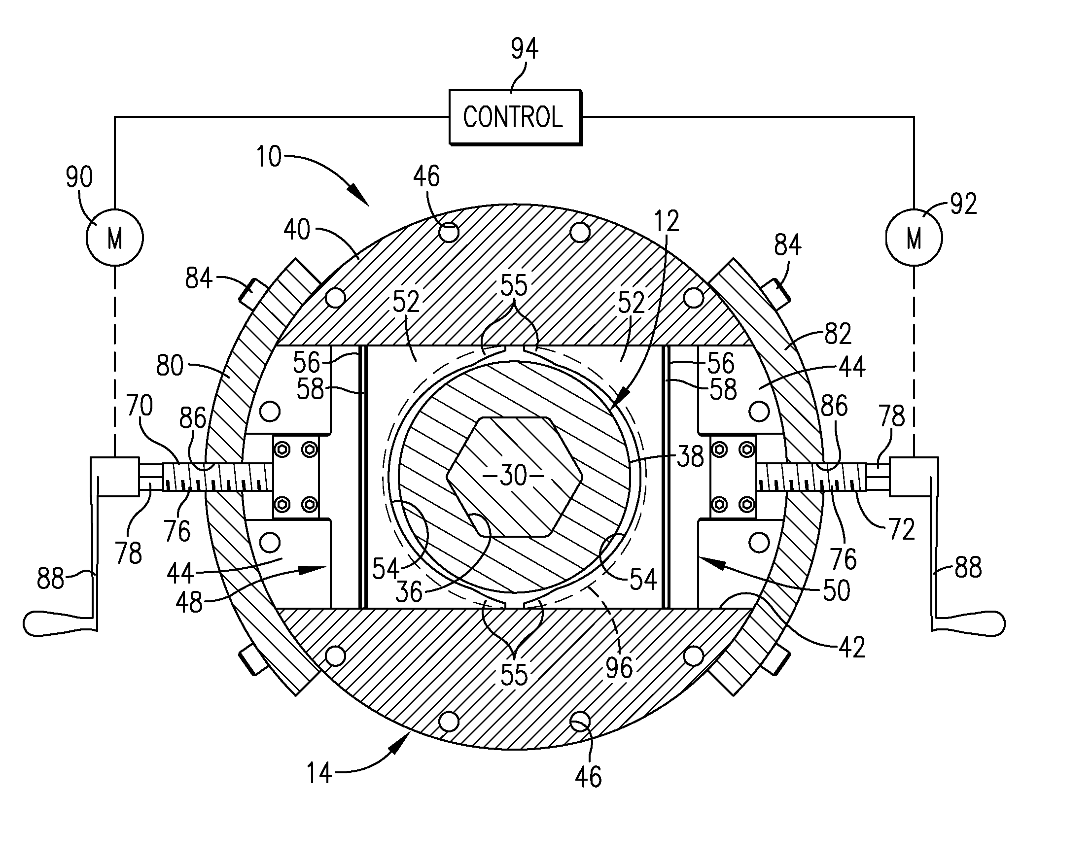
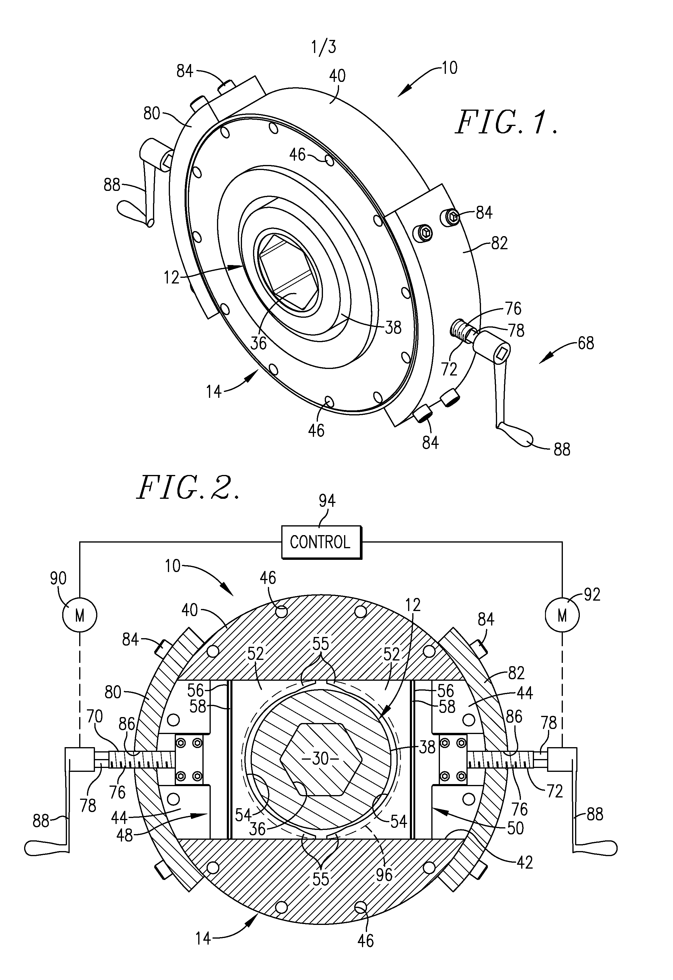
[0019] Turning now to the drawings, a restriction assembly 10 is illustrated in FIG. 1 and broadly includes a central shearlock element 12 and a mating, outboard restriction unit 14. The assembly 10 is designed for use with a single or twin screw extruder such as depicted in FIGS. 3 and 7, and is used to provide varying levels of flow restriction through the extruder barrel, in order to generate increased levels of back pressure and shear within the extruder.

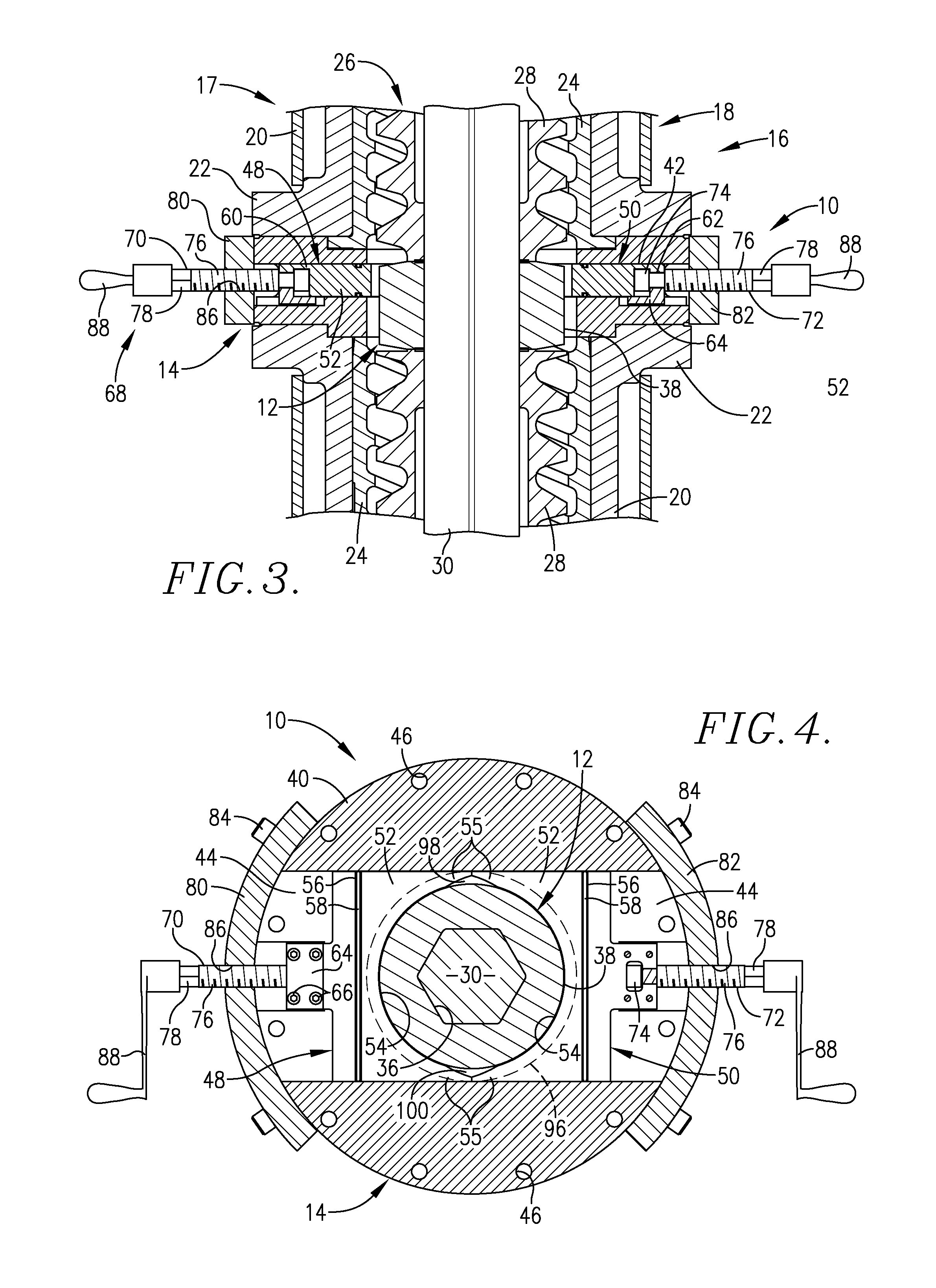
[0020] By way of general background, the assembly 10 is designed for use in a conventional single or twin screw extruder 16 illustrated in FIG. 3. In a single screw extruder 17, an elongated barrel 18 is provided, made up of a series of elongated, tubular, axially aligned and interconnected head section 20. Each of these sections 20 have a pair of end most, radially, enlarged flanges 22 that are designed to be interconnected to form a barrel 18. In the form shown, each of the head sections 20 is equipped with an inner, helicall...


PUM

PropertyMeasurementUnit
Thicknessaaaaaaaaaa
Lengthaaaaaaaaaa
Flow rateaaaaaaaaaa

Abstract

Flow restriction assemblies (10,10a) adapted to be mounted on single or twin screw extruders (17,102) in order to allow selective adjustment of material flow through the extruders (17,102), with consequent alteration in back pressure and shear conditions. The assemblies (10,10a) each have shearlock(s) (12,12a) mounted on the extruder drive shaft(s) (34,34a), together with restriction units (14,14a). The units (14,14a) have opposed flow restriction components (48,50,48a,50a) supported on opposite sides of the shearlock(s) (12,12a) and mounted for a substantially aligned and rectilinear back and forth sliding movement. In this fashion, the clearance between the inner surfaces (54,55,54a,55a) of the components (48,50,48a,50a) can be selectively adjusted. The assemblies (10,10a) are small in size and can be located at various points along the length of extruders (17,102)

Description

BACKGROUND OF THE INVENTION [0001] 1. Field of the Invention [0002] The present invention is broadly concerned with extrusion devices equipped with mid-barrel flow restriction assembly permitting selective alteration back pressure and shear conditions, in order to optimize extrusion cooking. More particularly, the invention is concerned with such extruders, and the flow restriction assemblies, wherein the later have a pair of opposed, slidable restriction components and drive apparatus for selective movement of the components toward and away from the extruder screw(s) so as to achieve selective flow restriction. [0003] 2. Description of the Prior Art [0004] Extrusion cooking devices are used in a multitude of contexts, e.g., for the fabrication of animal feeds and human food products. Generally speaking, single screw extruders include an elongated barrel having an inlet at one end and an outlet at the other equipped with a restricted orifice die. An elongated, flighted, axially rota...

Claims


Application Information

Patent Timeline
IPC IPC(8): B29C47/74B29C48/74
CPCB29C47/0009B29C47/38B29C47/0871B29C48/03B29C48/268B29C48/395
Inventor WILTZ, PHILIP B.ROKEY, GALEN J.
Owner WENGER MANUFACTURING INC
Why Eureka
Try Eureka