Reverser mechanism for uni-directional rotational driving of a wheel set

a technology of uni-directional rotation and reversing mechanism, which is applied in the direction of electromechanical clocks, timers, time indications, etc., can solve the problems of high friction force at high speeds, large assembly number of parts, and relative cumbersomeness, and achieves the effect of low cost and higher or equal performan

Active Publication Date: 2007-10-11
ETA SA MFG HORLOGERE SUISSE
View PDF6 Cites 20 Cited by
  • Summary
  • Abstract
  • Description
  • Claims
  • Application Information

AI Technical Summary

Benefits of technology

[0004]It is thus an object of the present invention to overcome the drawbacks of the aforecited prior art by providing a reverser mechanism comprising a smaller

Problems solved by technology

Such devices have the drawback of being relatively cumbersome and requiring the assembly of quite a large

Method used


Image

  • Reverser mechanism for uni-directional rotational driving of a wheel set
  • Reverser mechanism for uni-directional rotational driving of a wheel set
  • Reverser mechanism for uni-directional rotational driving of a wheel set

Examples


first embodiment

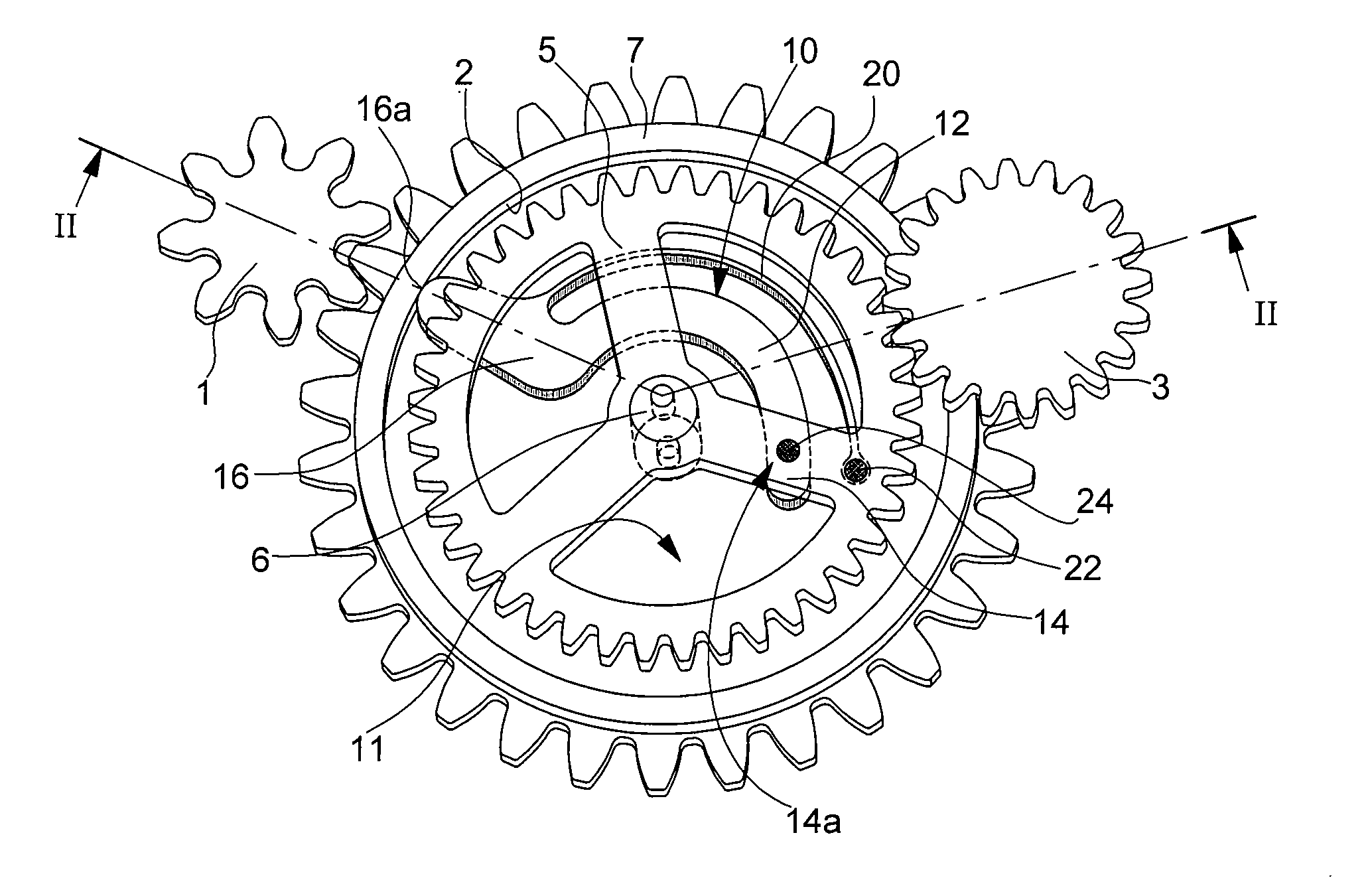
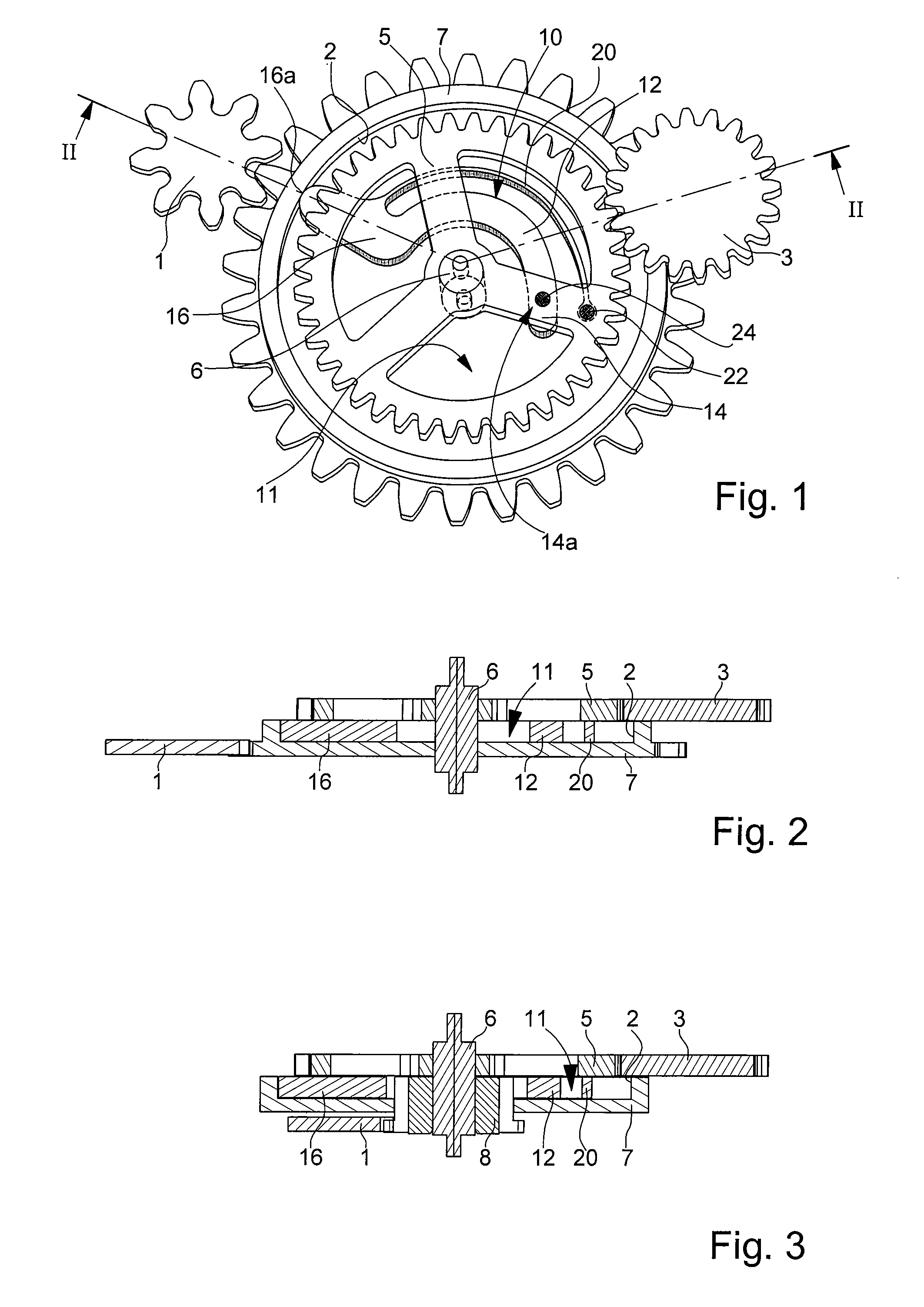
[0026]Referring first of all to FIGS. 1 and 2, we will describe below a reverser mechanism according to the invention, which will be illustrated by way of example by an automatic winding mechanism for a mechanical watch via an oscillating weight whose drive pinion 3 acts in a single direction to drive the first wheel set 1 of a kinematic reduction chain (not shown), the last wheel set of which is meshed with the barrel ratchet.

[0027]Drive pinion 3 of the oscillating weight meshes with a first toothed driving wheel 5 freely mounted on an arbour 6 pivoting between a plate and a bridge (not shown), or between any other armature for positioning the parts of a timepiece mechanism in relation to each other.

[0028]A second driven wheel 7 is positioned below drive wheel 5 and is also freely mounted on arbour 6 about which it rotates. It also comprises a toothing meshed with the first wheel set 1 of the kinematic chain.

[0029]Referring now to the cross-section of FIG. 2, it can be seen that dr...

second embodiment

[0032]As can be seen in the perspective diagram in FIG. 1, the angle formed by axis 6 with pivoting point 14a and point of abutment 16a is an obtuse angle, slightly less than 180°, meaning that the arm allows driving wheel 5 to rotate freely in one direction, without driving driven wheel 7, and conversely drives driven wheel 7 when driving wheel 5 is rotating in the other direction, as will be described in detail with reference to the

[0033]The cross-sectional diagram of FIG. 3 concerns a variant of the first embodiment regarding the position of the power take-off on driving wheel 5 and on driven wheel 7. As is clear, it is essential that driving wheel 5 and driven wheel 7 are free to rotate in relation to each other when coupling mechanism 10 is not active. In the example shown, driven wheel 7 no longer has a toothing but it is driven onto an additional pinion 8, which is itself secured to arbour 6, whereas driving wheel 5 remains freely mounted on said arbour 6. The first wheel set...

fourth embodiment

[0047]With reference now to FIGS. 13 to 16, a third and fourth embodiment will be described below concerning a “double direction” reverser mechanism, which basically consists in coupling a first single direction reverser mechanism, whose references will be followed by the letter “a”, and a second single direction reverser mechanism whose references will be followed by the letter “b”.


PUM


Abstract

The mechanism includes, mounted to rotate freely on an arbour 6, a driving wheel (5) driven by an oscillating drive pinion (3) and a driven wheel (7) meshed with the first wheel set (1) of a kinematic chain and comprising a dome (11) for housing a coupling device (10) comprising at least one bent locking arm (12) one end (14) of which has a pivoting point (14a, 14b) on the driving wheel (5) and the other end (16) of which has a point of abutment (16a) against the inner wall (2) of the dome (11) of the driven wheel (7) via the action of a spring (20) integral with said arm (12). The pivoting point (14b) preferably moves along a cam (21).
Application to automatic winding by an oscillating weight.

Description

[0001]This application claims priority from European Patent Application No. 06007364.0. filed 7 Apr. 2006, the entire disclosure of which is incorporated herein by reference.FIELD OF THE INVENTION[0002]The present invention concerns a reverser mechanism that drives the first wheel set of a kinematic chain in a single direction, whatever the direction of rotation of the drive pinion. Such reverser mechanisms are used in particular for automatically winding the barrel spring of a mechanical watch, or for driving the generator of any small portable electronic apparatus, the drive pinion also being set in movement by an oscillating weight.STATE OF THE ART[0003]Numerous automatic winding devices using an oscillating weight and reverser mechanism have already been proposed. These devices rely on the principles of cam or lever-click mechanisms, gear change mechanisms on two meshed wheels, only one of which is a drive wheel, or roller mechanisms, as disclosed for example in CH Patent No. 30...

Claims


Application Information

Patent Timeline
IPC IPC(8): G04B23/00
CPCF16D41/069F16D41/076G04B13/026G04B13/005G04B5/02G04B13/02
Inventor HELFER, JEAN-LUCCONUS, THIERRY
Owner ETA SA MFG HORLOGERE SUISSE
Why Eureka
Try Eureka