Dot Gain And Color Linearization Dual Calibration

Inactive Publication Date: 2007-10-11
HARUSH SHLOMO +2
View PDF4 Cites 8 Cited by
  • Summary
  • Abstract
  • Description
  • Claims
  • Application Information

AI Technical Summary

Benefits of technology

[0009] The present method of using bands as the measure for calibrating in the first step of Gila provides improved stability for both low density gray level values and also provides for repeatable fonts and line-work as the first step of calibration is performed. For example, in an embodiment of the invention, the pattern consists of bands (lines) of solid toner that are two dots wide, alternating with bands of no toner that are three dots wide. The average density of toner in such a pattern is more reliably correlated with the effective width of the laser beam (i.e. the width of the region over which the photosensitive surface is effectively discharged by the laser during one scan across the surface) than is the average density of toner in a prior art half-tone test pattern.
[0010] As in Gila et al, a solid test pattern is still u

Problems solved by technology

Furthermore, it was found that when the first step is performed, there are changes in the width of the lines in small fonts and line work.
However, as indicated above, while the procedure of Gila, et al., does give good values

Method used


Image

  • Dot Gain And Color Linearization Dual Calibration
  • Dot Gain And Color Linearization Dual Calibration
  • Dot Gain And Color Linearization Dual Calibration

Examples


Example

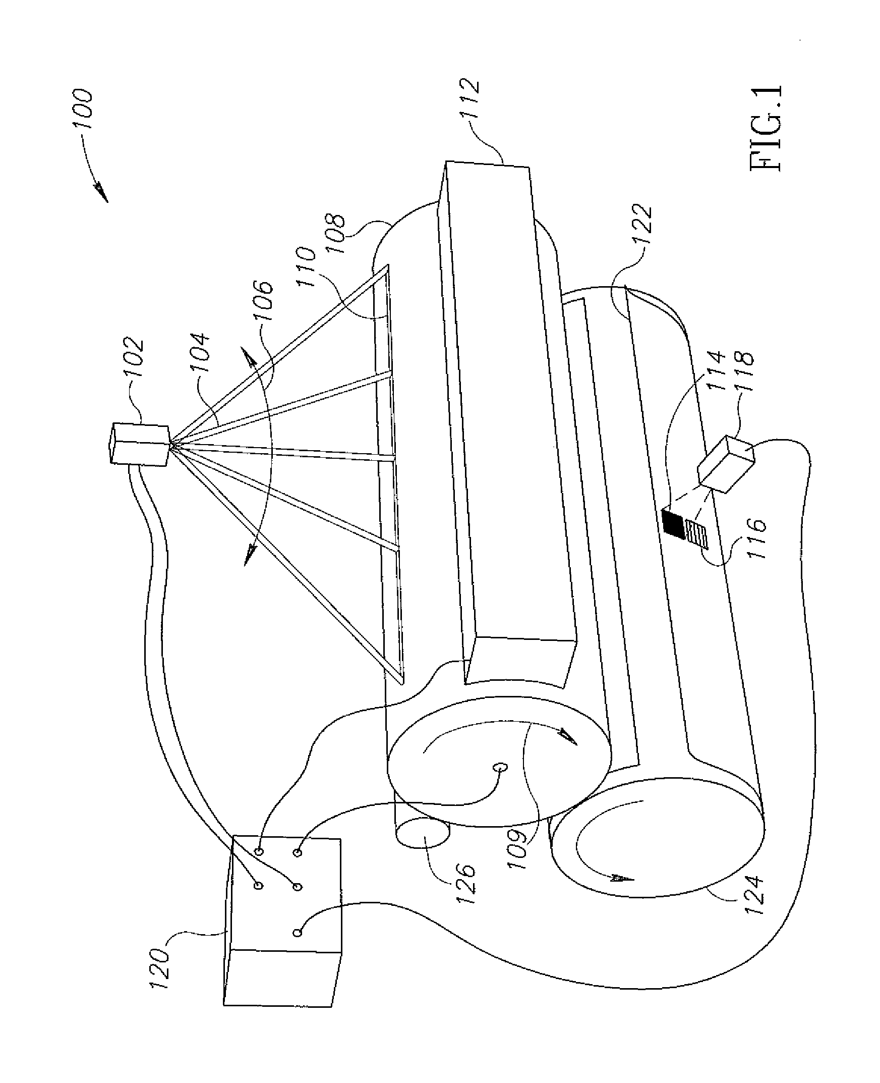
[0035]FIG. 1 shows an electrographic printer 100. A light source 102 produces a beam 104, for example from a laser, which swings back and forth, as indicated by arc 106, thereby scanning the surface of a charged photosensitive cylinder 108, along a line 110, and locally discharging the surface when the laser beam is turned on. The scanning is performed, for example, by a mirror, not shown, in light source 102, which rotates or swings back and forth while the beam reflects from it. Photosensitive cylinder 108 rotates, in a direction indicated by arrow 109. Scanning beam 104 produces a two-dimensional latent image of charged and discharged regions on the surface of photosensitive cylinder 108, by turning on and off, or modulating its power, as the beam scans and the photosensitive cylinder rotates. The latent image is developed into a toner image when the surface passes a development station 112.

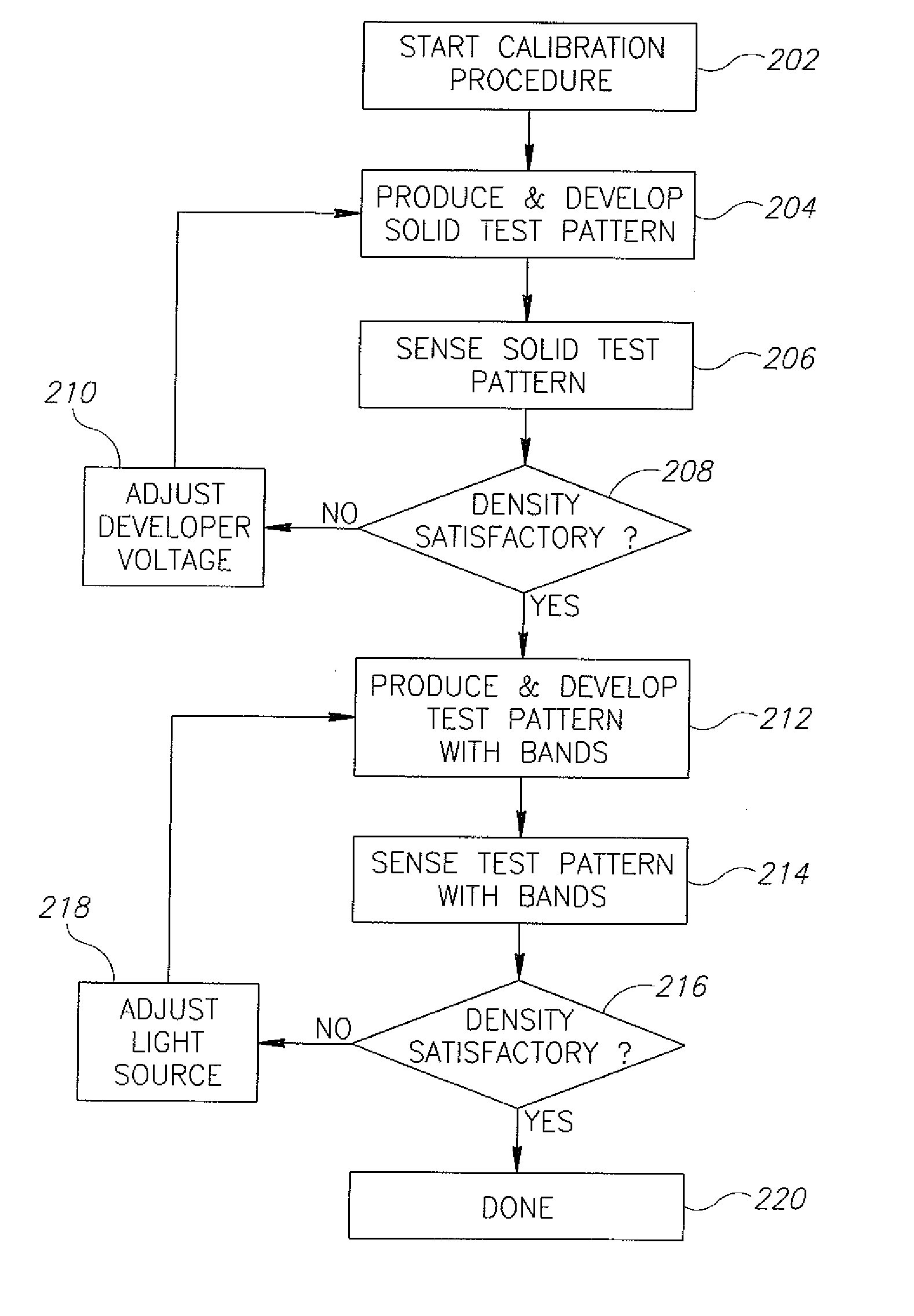
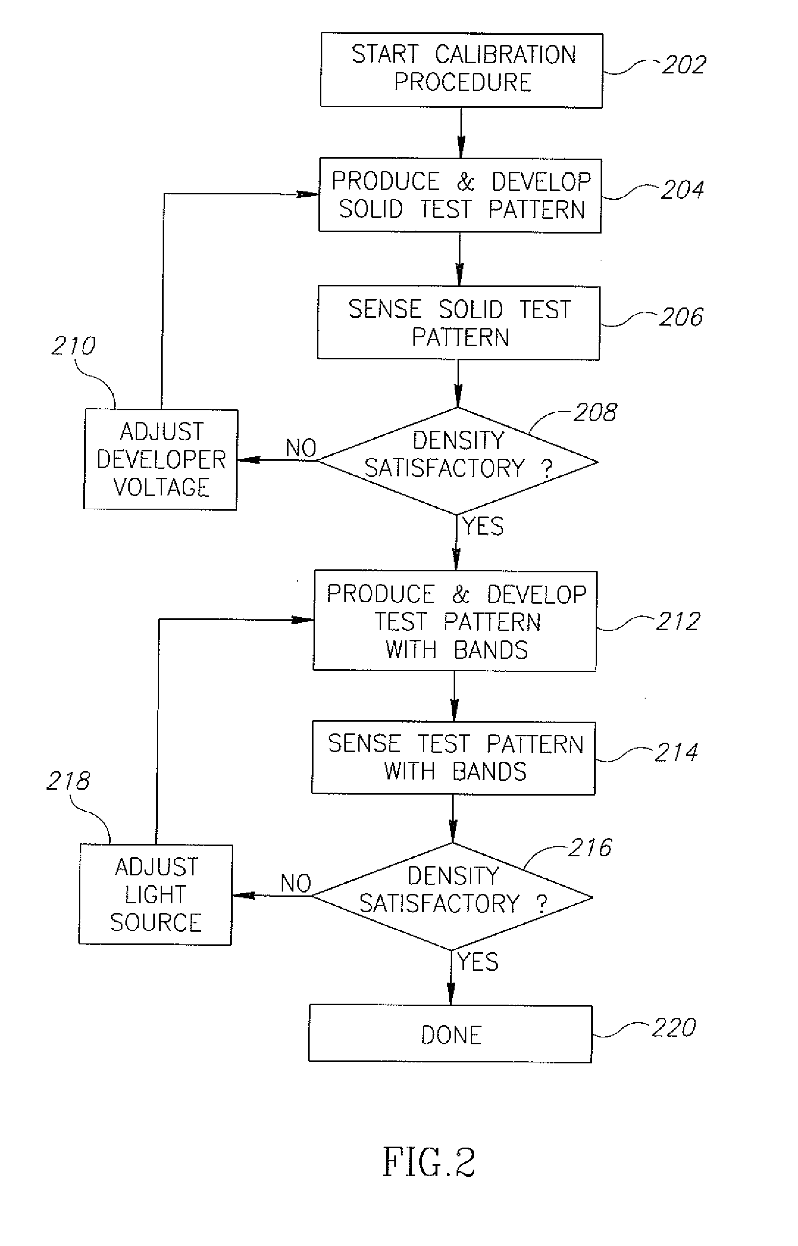
[0036] From time to time printer 100 undergoes a calibration procedure, in which a solid ...


PUM


Abstract

A method of calibrating an electrographic printer, comprising: a) producing a latent image of a banded test pattern and a solid test pattern, using a beam of a light source of controllable power; b) developing the banded test pattern and the solid test pattern with a toner, utilizing an electrode with a developing voltage; c) measuring an average toner optical density of the developed banded test pattern and an average optical toner density of the developed solid test pattern; and d) adjusting one or both of (i) the developing voltage and (ii) the power and/or the diameter of the beam such that the measured average toner optical density of the two patterns matches, within predetermined limits, desired optical densities.

Description

FIELD OF THE INVENTION [0001] The field of the invention is electrographic printers. BACKGROUND OF THE INVENTION [0002] In electrographic printers, a modulated light source, typically a laser, scans the charged surface of a photosensitive cylinder to produce a latent image from a digital image file, by discharging parts of the surface. After the discharge, regions that are intended to receive toner are at a first voltage, and background regions are at a second voltage. Regions that are intended to be of intermediate apparent optical density are typically produced by using half-tone patterns in the digital image file, so that each location on the photosensitive cylinder is either at the first voltage or the second voltage. The latent image is then developed by exposing the surface to an electrographic toner, in the presence of an electrode which typically has a developer voltage between the first and second voltage, so that the sign of the electric field differs for regions at the fi...

Claims


Application Information

Patent Timeline
IPC IPC(8): G03G15/00G03G15/043G03G15/06
CPCG03G9/0821G03G15/043G03G15/065G03G2215/00042G03G15/5062G03G2215/00067H04N1/40006H04N1/4078G03G15/5058G03G2215/00059
Inventor HARUSH, SHLOMOBRAVERMAN, GREGORYSHELEF, EYAL
Owner HARUSH SHLOMO
Why Eureka
Try Eureka