Hot runner system for injection molding machine

a technology of injection molding machine and nozzle, which is applied in the field of nozzle combining structure of hot runner system for injection molding machine, can solve the problems of nozzle b, /b> fracture, etc., and achieve the effects of reducing thermal loss, preventing nozzle breakage, and large satisfaction

Inactive Publication Date: 2007-10-11
YUDO
View PDF16 Cites 15 Cited by
  • Summary
  • Abstract
  • Description
  • Claims
  • Application Information

AI Technical Summary

Benefits of technology

[0017] Accordingly, the present invention is to solve the problem above mentioned, and therefore the object of the present invention is to provide the hot runner system for an injection molding machine which is capable of increasing durability of the nozzle by preventing a fracture of the nozzle by maintaining the balance of force applied into the axial direction of the nozzle uniformly irrespective of a volume change of the manifold by the thermal expansion.
[0020] In a still another embodiment, the manifold guide bushing includes a plurality of projection for contacting the piston guide bushing at an inner circumferential surface of the manifold guide bushing to reduce a contact area with an outer surface of the piston guide bushing of the nozzle thereby reducing the thermal loss caused by a contact with the piston guide bushing.
[0021] Thus the hot runner system for injection molding machine according to the present invention can maintain uniformly the balance of force applied to the axial direction of the nozzle irrespectively of the volume variation of the manifold caused by the thermal expansion thus preventing the break of the nozzle effectively, thereby providing large satisfaction to users by increasing largely durability.

Problems solved by technology

However, the typical hot runner system 10 described above has a problem that a fracture on the nozzle 20 will be taken place in part or totally due to unbalance of force applied to the axial direction of the nozzle 20 and a bending stress applied to the nozzle 20 while the manifold 15 is thermally expanded on injecting melted resin into the mold, because an upper portion of the nozzle 20 is firmly fixed to the manifold 15 and a lower portion of the nozzle 20 is fixed to the surface of the mold to inject the melted resin into the inside of the mold using the typical hot runner system 10.

Method used


Image

  • Hot runner system for injection molding machine
  • Hot runner system for injection molding machine
  • Hot runner system for injection molding machine

Examples


Embodiment Construction

[0029] Hereinafter, The preferred embodiment of the present invention will be now described in detail with respect to accompanying drawings.

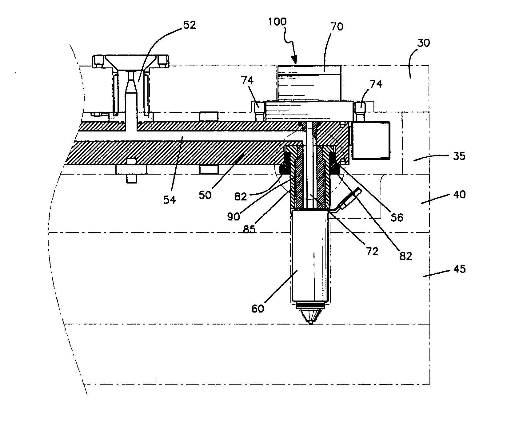
[0030]FIG. 3 shows a cross-sectional view of a nozzle combining structure of a hot runner system for injection molding machine according to an embodiment of the present invention. FIG. 4 shows an exploded perspective view of the nozzle combining structure of the hot runner system for injection molding machine according to an embodiment of the present invention. FIG. 5 shows a cross-sectional view of a manifold of the nozzle combining structure of the hot runner system for injection molding machine according to an embodiment of the present invention in which the nozzle is not thermally expanded. FIG. 6 shows a cross-sectional view of a manifold of the nozzle combining structure of the hot runner system for injection molding machine according to an embodiment of the present invention in which the nozzle is thermally expanded.

[0031] As described ...


PUM

PropertyMeasurementUnit
temperatureaaaaaaaaaa
structureaaaaaaaaaa
diameteraaaaaaaaaa

Abstract

The present invention relates to a nozzle combining structure of a hot runner system for an injection molding machine capable of increasing durability of the nozzle. To achieve the object of the present invention, the present invention comprises a nozzle combining structure for a hot runner system for an injection molding machine comprising: a manifold having a resin injecting hole extending therethrough in its inner portion through which a resin flows and a nozzle seated groove formed in an outer peripheral surface of an end of the resin injecting hole, a nozzle being seated in the groove; a nozzle having a piston guide bushing formed at its upper end inserted into the nozzle seated groove of the manifold, for dispensing the resin injected from the resin injecting hole of the manifold through the piston guide bushing into a mold; a manifold guide bushing for surrounding and threadedly engaging with an upper portion of the piston guide bushing of the nozzle, the upper end of the manifold guide bushing having a diameter smaller than that of the nozzle seated groove of the manifold so that the upper end of the manifold guide bushing is inserted into the nozzle seated groove of the manifold; and a fastening bushing for receiving an outer surface of the manifold guide bushing and threadedly engaging with an inner circumferential surface defining the nozzle seated groove of the manifold so that the manifold guide bushing is fastened by the fastening bushing to the inner circumferential surface defining the nozzle seated groove of the manifold.

Description

CROSS-REFERENCE TO RELATED APPLICATION [0001] The present application claims priority from Korean Patent Application No. 10-2006-0032488, filed Apr. 10, 2006, the entire contents of which are hereby incorporated by reference. [0002] 1. Field of the Invention [0003] The present invention relates to a nozzle combining structure of a hot runner system for an injection molding machine capable of increasing durability of the nozzle. [0004] 2. Background Art [0005] Generally, a Hot Runner System refers to a system for injecting melted resin into the inside of an injection mold under high pressure while maintaining the melted resin at high temperature on injecting the melted resin into the injection mold. [0006] This hot runner system has been researched and developed constantly for reducing the wasted resin in manufacturing a plastic injection product. As is shown in FIGS. 1 and 2, the typical hot runner systems are implemented inside a mold in which a plurality of flat plates, i.e., a cl...

Claims


Application Information

Patent Timeline
Patent Type & Authority Applications(United States)
IPC IPC(8): B29C45/27
CPCB29C45/27B29C45/2806B29C2045/2798B29C2045/2764B29C2045/2772B29C2045/2762B29C45/17B29C45/20B29C45/22
Inventor YU, YOUNG HEE
Owner YUDO
Why Eureka
Try Eureka