Filter with memory, communication and pressure sensor

a technology of pressure sensor and filter, applied in the field of filter with memory, communication and pressure sensor, can solve the problems of unsatisfactory treatment of additional areas, and achieve the effect of improving the reliability and validity of integrity tests

Active Publication Date: 2007-10-18
MILLIPORE CORP
View PDF67 Cites 61 Cited by
  • Summary
  • Abstract
  • Description
  • Claims
  • Application Information

AI Technical Summary

Benefits of technology

[0010] The use of this device is beneficial to many applications. For example, the ability to monitor transmembrane pressure across each filter individually in a multiple filter configuration improves the reliability and validity of an integrity test. This also allows the integrity of each filtering element to be individually determined in situ. The ability to monitor the transmembrane pressure within the filter housing also enables the plugging of multi-layer filters to be monitored, allowing the life of the filter to be estimated.

Problems solved by technology

Despite the improvements that have occurred through the use of RFID tags, there are additional areas that have not been satisfactorily addressed.

Method used


Image

  • Filter with memory, communication and pressure sensor
  • Filter with memory, communication and pressure sensor
  • Filter with memory, communication and pressure sensor

Examples


Embodiment Construction

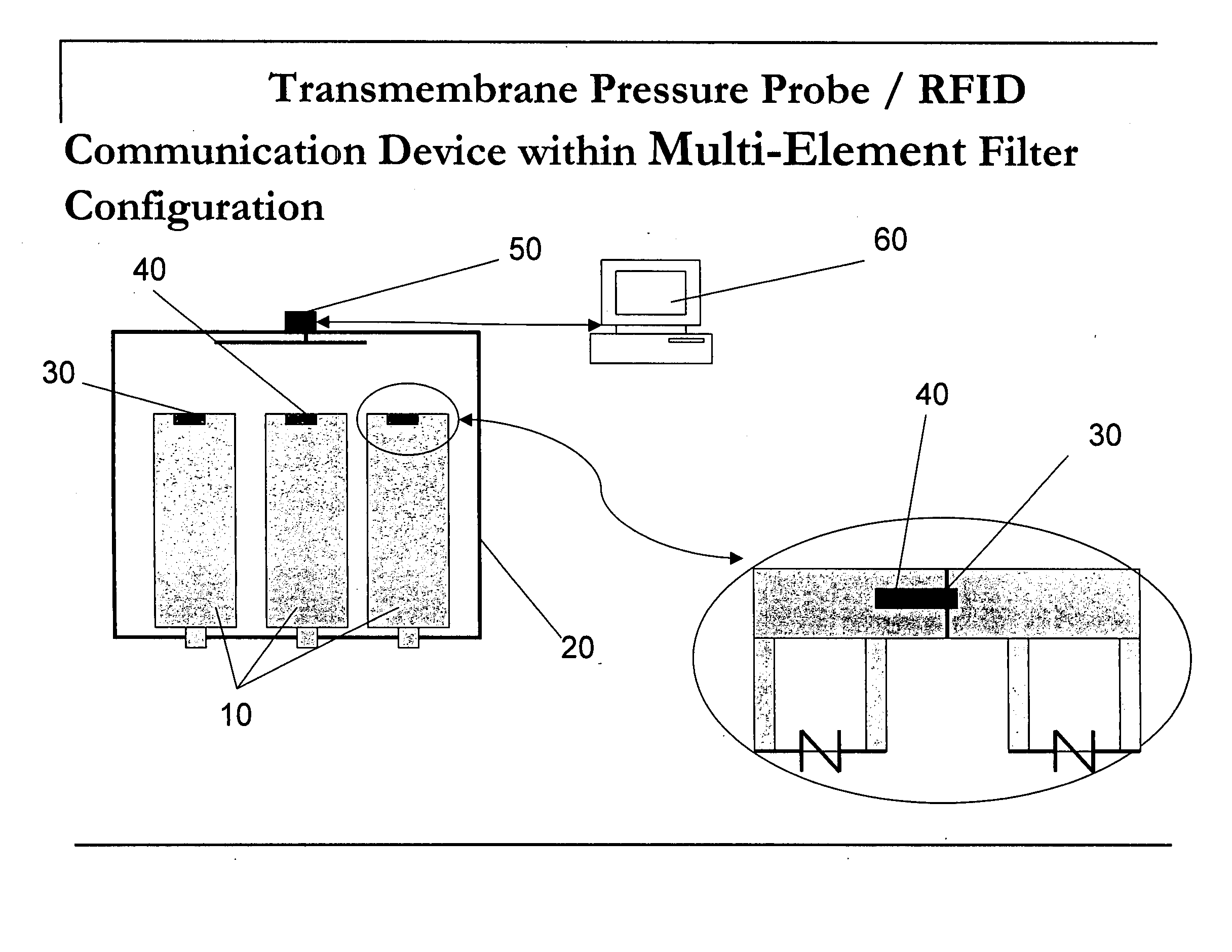
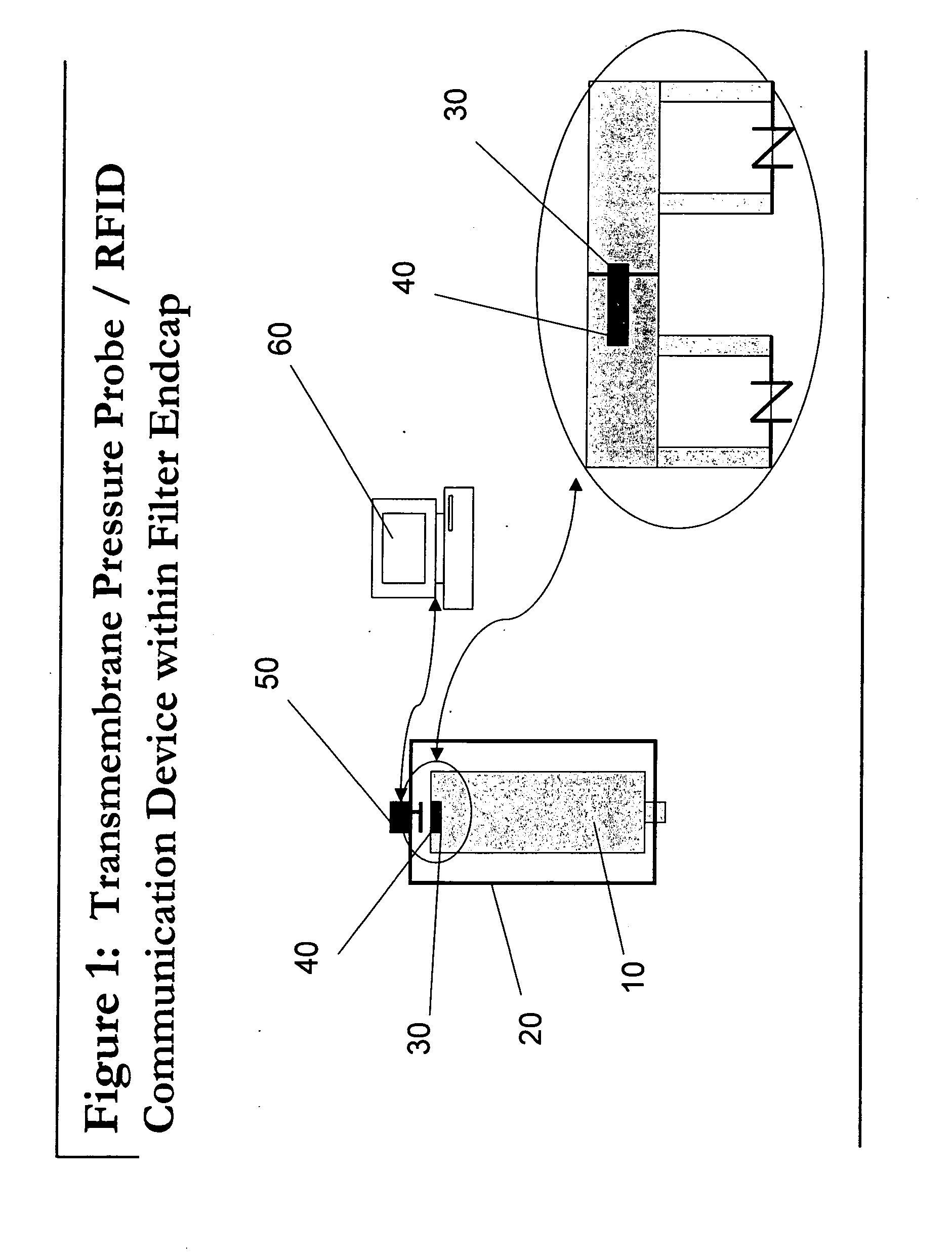
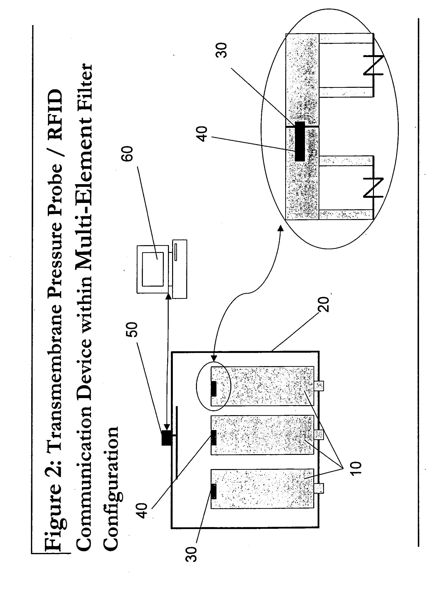
[0016]FIG. 1 illustrates a representative filtering system in accordance with the present invention. The filter element 10 is enclosed with a housing 20. The filter element can be simply a porous material, such as pleated paper or PVDF (Polyvinylidene fluoride) membrane. In an alternative embodiment, shown in FIG. 2, multiple filter elements 10 are enclosed within one housing 20. Alternatively, the filter element may comprise a frame, such as of plastic, and a porous material. Located in close proximity of, preferably affixed to, and most preferably embedded in, the end cap of filter element 10 is a pressure sensor 30. This sensor 30 is capable of generating an output, which varies as a function of the pressure of the surrounding environment. In another embodiment, the sensor is a differential sensor, whereby its output is a function of the difference is pressure between two areas. This output can be in the form of an analog voltage or current, or can be a digital value or pulse. In...


PUM

PropertyMeasurementUnit
temperaturesaaaaaaaaaa
flow rateaaaaaaaaaa
flow rateaaaaaaaaaa

Abstract

The present invention describes a system and method for accurately measuring the pressure within a filter housing. A pressure sensor and a communications device are coupled so as to be able to measure and transmit the pressure within the filter housing while in use. This system can comprise a single component, integrating both the communication device and the pressure sensor. Alternatively, the system can comprise separate sensor and transmitter components, in communication with one another. In yet another embodiment, a storage element can be added to the system, thereby allowing the device to store a set of pressure values. The use of this device is beneficial to many applications. For example, the ability to read pressure values in situ allows integrity tests to be performed without additional equipment. In addition, integrity testing for individual filters within multi-filter configurations is possible.

Description

BACKGROUND OF THE INVENTION [0001] The use of RFID tags has become prevalent, especially in the management of assets, particularly those applications associated with inventory management. For example, the use of RFID tags permits the monitoring of the production line and the movement of assets or components through the supply chain. [0002] To further illustrate this concept, a manufacturing entity may adhere RFID tags to components as they enter the production facility. These components are then inserted into the production flow, forming sub-assemblies in combination with other components, and finally resulting in a finished product. The use of RFID tags allows the personnel within the manufacturing entity to track the movement of the specific component throughout the manufacturing process. It also allows the entity to be able to identify the specific components that comprise any particular assembly or finished product. [0003] In addition, the use of RFID tags has also been advocate...

Claims


Application Information

Patent Timeline
Patent Type & Authority Applications(United States)
IPC IPC(8): G01M3/02G01N15/08
CPCB01D35/143B01D61/147B01D61/22B01D65/102B01D2313/44B01D2201/291B01D2201/52B01D2201/56B01D2311/14B01D65/104
Inventor DILEO, ANTHONYHUBBARD, JOHN DANA
Owner MILLIPORE CORP
Why Eureka
Try Eureka