Traffic ballast system

a technology of traffic ballast and ballast plate, which is applied in the field of traffic ballast plate, can solve the problems of failure to teach a base with insertable uprights for holding, and achieve the effect of high portability and compact storag

Inactive Publication Date: 2007-10-18
DVORACEK JOE
View PDF8 Cites 28 Cited by
  • Summary
  • Abstract
  • Description
  • Claims
  • Application Information

AI Technical Summary

Benefits of technology

[0009] A still further objective is to provide such a sign structure and system that is highly portable and compact in storage due to nesting features.

Problems solved by technology

However, the prior art fails to teach a base with insertable upright for holding a sign, wherein the base is made of a highly resilient material and has an insert of a highly rigid structural material for securing the inserted upright.

Method used


Image

  • Traffic ballast system
  • Traffic ballast system
  • Traffic ballast system

Examples


Embodiment Construction

[0024] The above described drawing figures illustrate the described apparatus and its method of use in at least one of its preferred, best mode embodiment, which is further defined in detail in the following description. Those having ordinary skill in the art may be able to make alterations and modifications what is described herein without departing from its spirit and scope. Therefore, it must be understood that what is illustrated is set forth only for the purposes of example and that it should not be taken as a limitation in the scope of the present apparatus and method of use.

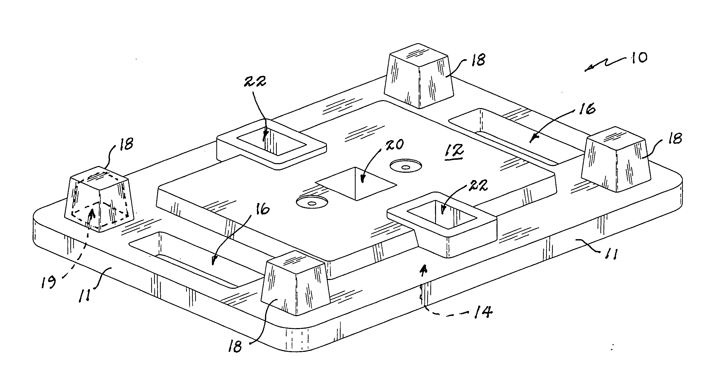
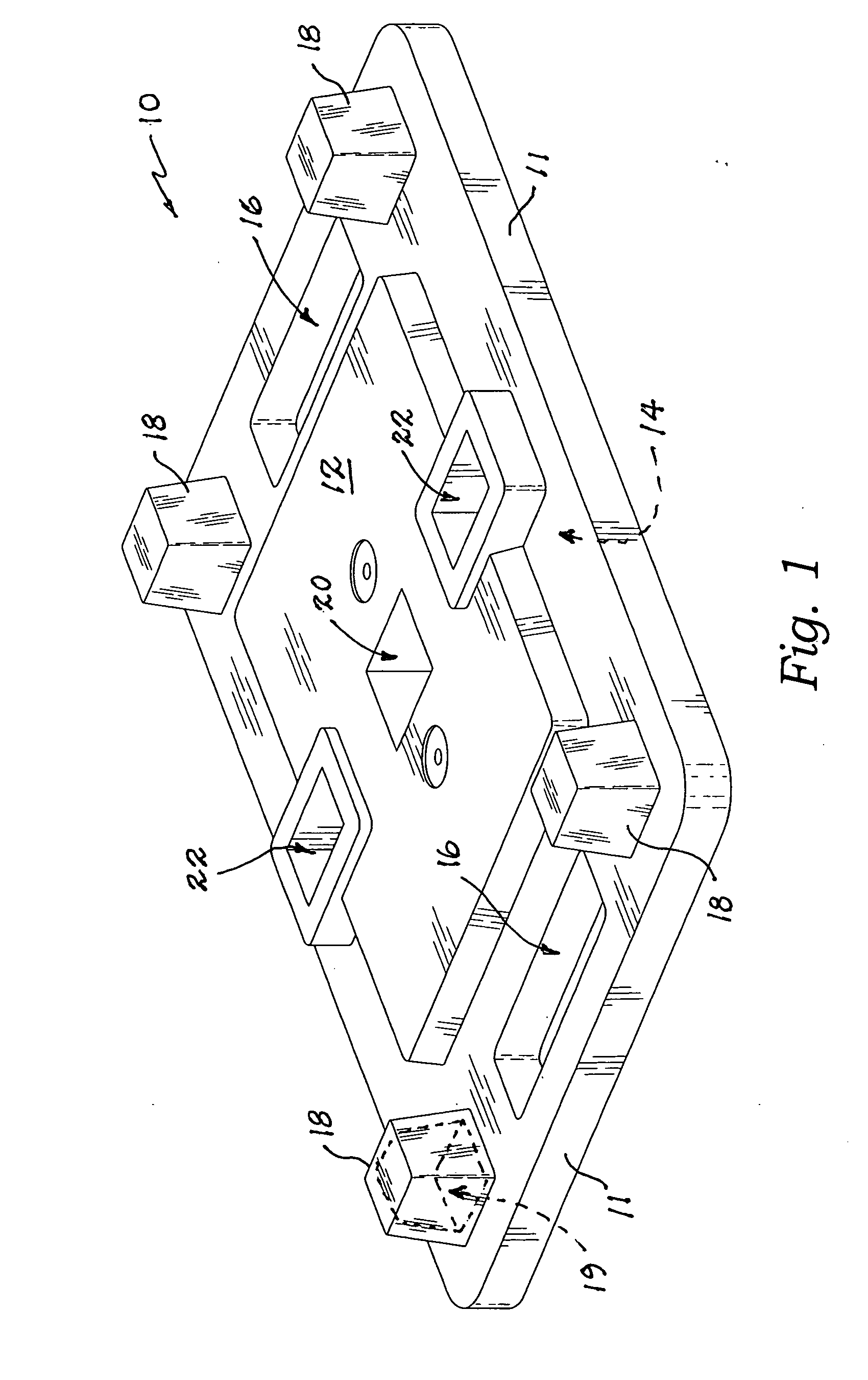
[0025] The presently described apparatus is a traffic ballast system for supporting signs, reflective surfaces and symbols for directing and informing motor traffic. The apparatus is constructed of a base 10 whose material makeup is preferably one of natural or synthetic rubber but also can be constructed of any rubber-like material such as a rubberized plastic. Generally, this material is not rigid and t...


PUM


Abstract

A traffic ballast system has a base of a non-rigid, resilient, shock absorbing material, the base providing a top surface and a spaced apart bottom surface. At least one strut aperture extends through the top surface. A receiver plate of a rigid structural material is engaged with the base below the top surface. At least one vertical strut supporting at least one sign has a lower end engaged within the at least one strut aperture, and further rigidly engaged with the receiver plate.

Description

FIELD OF THE PRESENT DISCLOSURE [0001] This disclosure relates generally to road signs and more particularly to a traffic sign system with interchangeable elements able to be adapted to various configurations. DESCRIPTION OF RELATED ART INCLUDING INFORMATION DISCLOSED UNDER 37 CFR 1.97 AND 1.98 [0002] Brown et al., U.S. Pat. No. D406,543 describes a traffic channelizer design. Bent et al., U.S. Pat. No. D412,131 describes a traffic channelizing system design. Alt, U.S. Pat. No. D419,901 describes a safety marking pylon design. Abrams, U.S. Pat. No. 3,380,428 describes a traffic guide post means comprising a post member and a base member of mutually interfitting relationship. Lyons et al., U.S. Pat. No. 3,933,118 describes a signal device combining a fluorescent or phosphorescent light tube and a weighted base designed to be thrown or dropped from a vehicle as a warning marker. The light tube is preferably of the chemically actuated type and the base preferably has four resilient leg...

Claims


Application Information

Patent Timeline
Patent Type & Authority Applications(United States)
IPC IPC(8): A47B91/00
CPCG09F15/0056E01F9/692
Inventor DVORACEK, JOE
Owner DVORACEK JOE
Why Eureka
Try Eureka