
Top-emitting OLED display having transparent touch panel

a technology of organic light-emitting diodes and display screens, which is applied in the direction of electronic switching, pulse techniques, instruments, etc., can solve the problems of resistive touch devices and electrolurminescent devices manufactured on two surfaces of transparent substrates that are likely to get scratches during the manufacturing process, resistive touch devices have low sensitivity, and resistive touch devices are relatively low sensitivity, so as to reduce electromagnetic interference

Inactive Publication Date: 2007-10-18
RITDISPLAY
View PDF5 Cites 144 Cited by
  • Summary
  • Abstract
  • Description
  • Claims
  • Application Information

AI Technical Summary

Benefits of technology

[0010]An objective of the present invention is to provide a top-emitting OLED display having a transparent touch panel, which has various advantages such as high light transmittance, high sensitivity and anti-scratch.
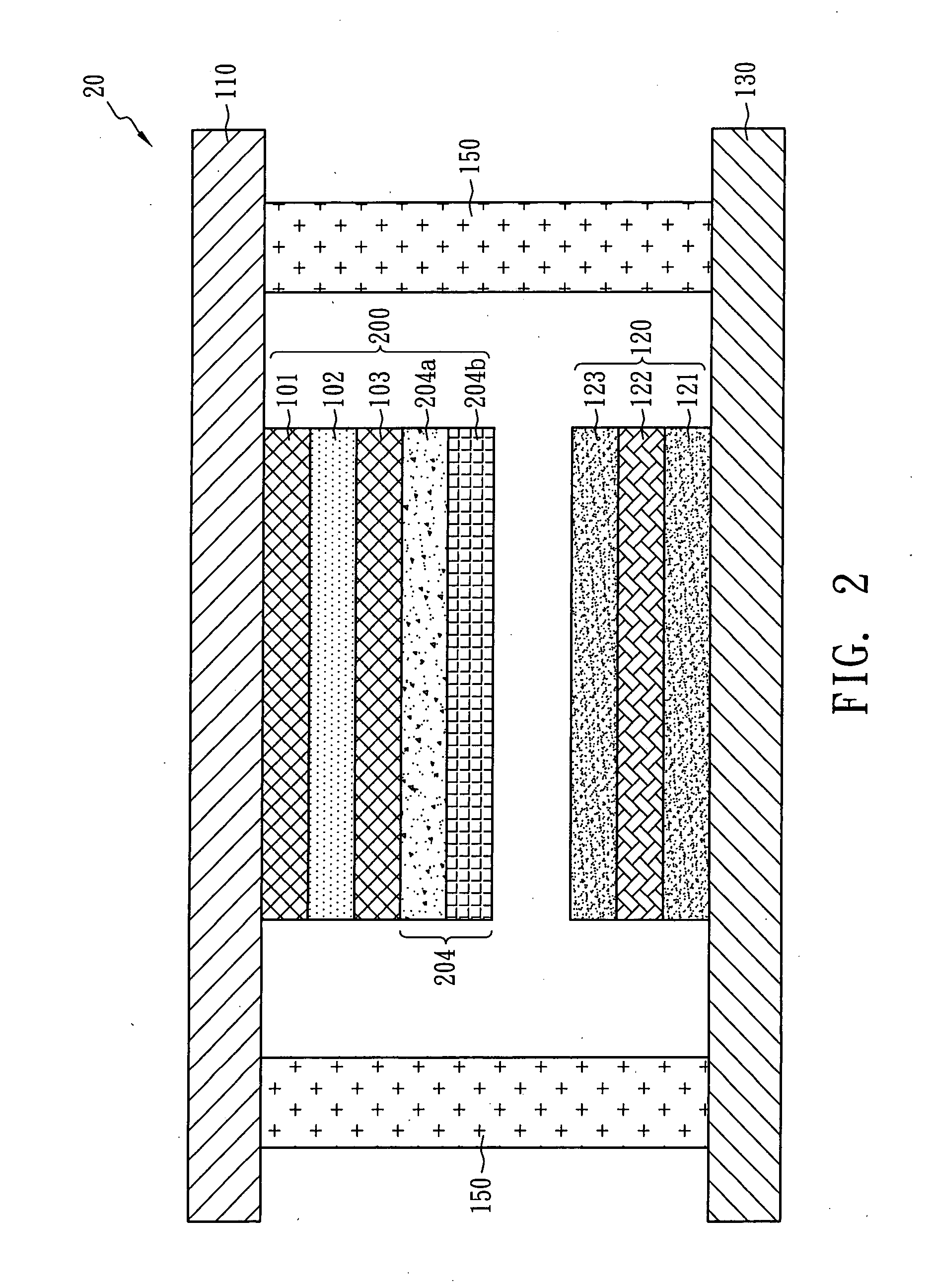
[0015]The capacitive touch device can further comprise an electromagnetic shielding layer having a polymer insulating layer and a transparent conductive layer. The electromagnetic shielding layer can effectively reduce electromagnetic interfering between the OLED structure and the capacitive touch device.

Problems solved by technology

However, the resistive touch device and the electrolurminescent device fabricated on two surfaces of the transparent substrate are likely to get scratches during the manufacturing process.
Moreover, the sensitivity of the resistive touch device is relatively low.
However, the resistive touch device has low sensitivity, and can adequately detect any input only when being pressed by an object with a sharp end, such as a pen.
Therefore, the resistive touch device is easy to be scratched in use.
Moreover, when the organic light emitting display is combined with the cover, the resistive touch device fabricated on the cover is easy to be damaged.
However, the fabricating method disclosed in US 2004 / 0090426 A1 is rather complicated, and the service life of the organic luminescent material is shortened due to the process of the resistive touch device.
Moreover, the sensitivity of the resistive touch device is relatively low.

Method used


Image

  • Top-emitting OLED display having transparent touch panel
  • Top-emitting OLED display having transparent touch panel
  • Top-emitting OLED display having transparent touch panel

Examples


Embodiment Construction

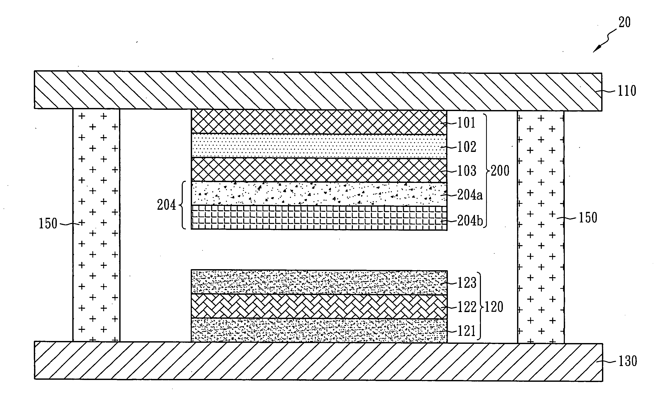
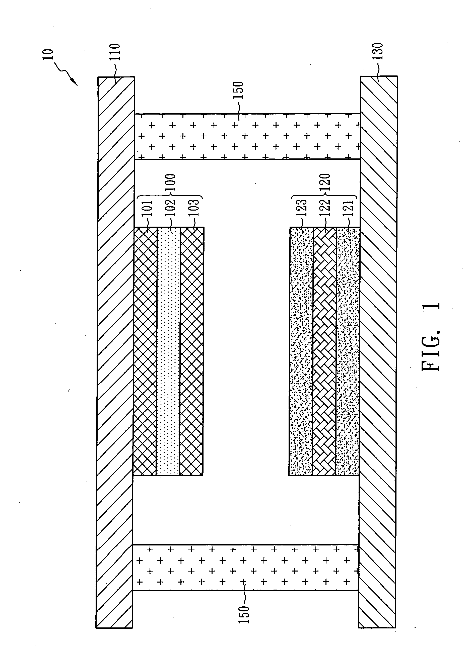
[0021]FIG. 1 is a schematic sectional view of a top-emitting OLED display having a transparent touch panel in accordance with the first embodiment of the present invention. The transparent touch screen 10 includes a substrate 130, an upper cover plate 110, an OLED device 120, a capacitive touch device 100 and a sealant layer 150.

[0022]The OLED device 120 is stacked on the substrate 130, and the capacitive touch device 100 is stacked on the surface of the upper cover plate 110. The sealant layer 150 combines the substrate 130 and the upper cover plate 110 such that the OLED device 120 is sealed in an enclosed space.

[0023]The capacitive touch device 100 includes a first transparent conductive layer 101, an isolating layer 102 and a second transparent conductive layer 103 sequentially formed on the upper cover plate 110. However, the structure of the capacitive touch device is not limited to the present embodiment, that is, the second transparent conductive layer and the first transpar...


PUM


Abstract

A top-emitting OLED display having a transparent touch panel includes a substrate, an upper cover plate, an OLED display device, a capacitive touch device and a sealant layer. The OLED device is stacked on the substrate, the capacitive touch device is stacked on the upper cover plate, and the sealant layer combines the substrate and the upper cover plate such that the OLED device and the capacitive touch device are enclosed between the substrate and the upper cover plate. The capacitive touch device includes a first transparent conductive layer, an isolating layer, a second transparent conductive layer and an electromagnetic shielding layer sequentially formed on the upper cover plate. The electromagnetic shielding layer can effectively reduce the electromagnetic interfering between the OLED device and the capacitive touch device.

Description

BACKGROUND OF THE INVENTION[0001]1. Field of the Invention[0002]The present invention relates to a transparent touch screen, and more particularly to a top-emitting OLED (Organic Light Emitting Diode) display having a transparent touch panel.[0003]2. Description of the Related Art[0004]Currently, OLED display devices are divided into two light emitting modes that are the bottom-emitting mode and the top-emitting mode. Since rays emitted by the organic light emitting layer of a bottom-emitting OLED may be shielded by the thin-film transistors (TFT) on the substrate, the aperture ratio is reduced by the TFTs. Therefore, the top-emitting OLED is an effective solution to improve the ratio of effective light emitting areas to total areas such that is superior to a conventional active LED display apparatus.[0005]The touch screen is a simple, humanized and space-saving input apparatus widely applied in tourist guiding systems, automatic teller machines (ATMs), palm computers, point-of-sale...

Claims


Application Information

Patent Timeline
IPC IPC(8): G06F3/041
CPCG06F3/0412H01L27/323H01L51/524H03K2217/960785H03K17/962H03K2017/9602H03K2217/960755H01L2251/5315G06F3/044H10K59/40H10K2102/3026H10K59/871H10K50/841
Inventor LAI, YUANG WEI
Owner RITDISPLAY
Learn More