Cable connection interface for rack mount apparatus, and rack mount apparatus

Inactive Publication Date: 2007-10-18
FUJITSU LTD
View PDF22 Cites 29 Cited by
  • Summary
  • Abstract
  • Description
  • Claims
  • Application Information

AI Technical Summary

Benefits of technology

[0050] In addition, it is also appropriate that the panel has a rotary shaft whose both ends are rotatably supported by the rack and two surface portions intersecting each other on the axis of the rotary shaft and one surface portion of the two surface portions intersecting each other is brought into contact with the device or the withdrawn member while a connection portion with the interface cable to be connected to the device is placed on the other surface portion of the two surface portions. This contributes to the improvement of the beauty of the device. Moreover, because of the considerable improvement of the visibility for the worker, it is possible to shorten the work time taken for the installation

Problems solved by technology

Concretely, if the front surfaces thereof are covered thereby, while each of the shelves 100 are in service, the worker cannot insert or extract a substrate unit 91 into or from each of the shelves 100 adjacent vertically to each other, so difficulty is experienced in conducting the operations such as restoration processing at the occurrence of a trouble, maintenance and replacement.
Yet moreover, when the fan unit 110 is attached onto a side surface of the shelf 100, the horizontal width of the shelf 100 increases, which makes it difficult to achieve the size reduction of the shelf 100.
Therefore, the installation of racks Back-To-Back-mounted makes it difficult to sufficiently secure the working space, which makes it extremely difficult to the worker to conduct the operations such as connection change of the connector section 120 provided on a rear surface of each of the shelves 100 or which makes it impossible to conduct the operation

Method used


Image

  • Cable connection interface for rack mount apparatus, and rack mount apparatus
  • Cable connection interface for rack mount apparatus, and rack mount apparatus
  • Cable connection interface for rack mount apparatus, and rack mount apparatus

Examples


first embodiment

[0066] (A) Description of First Embodiment of the Present Invention

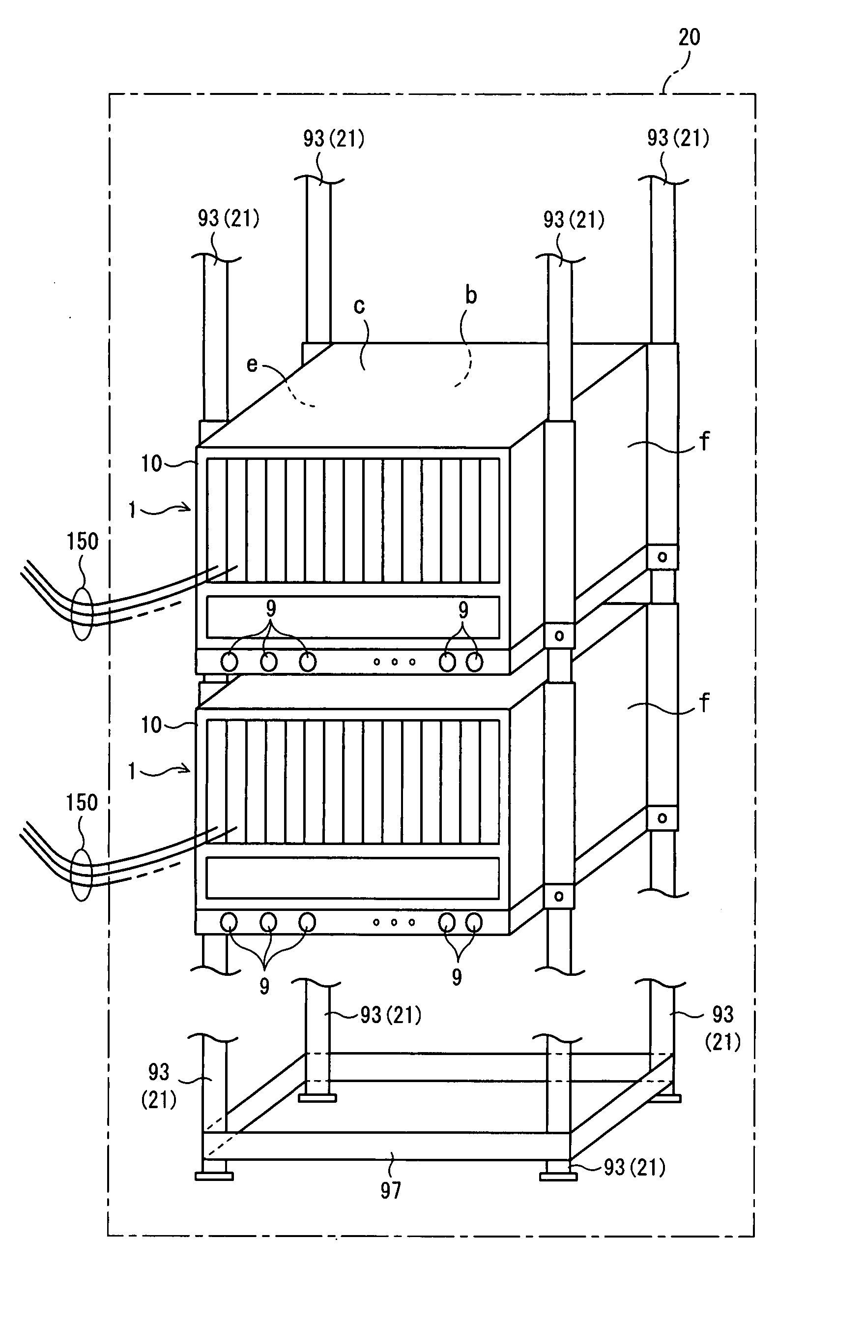
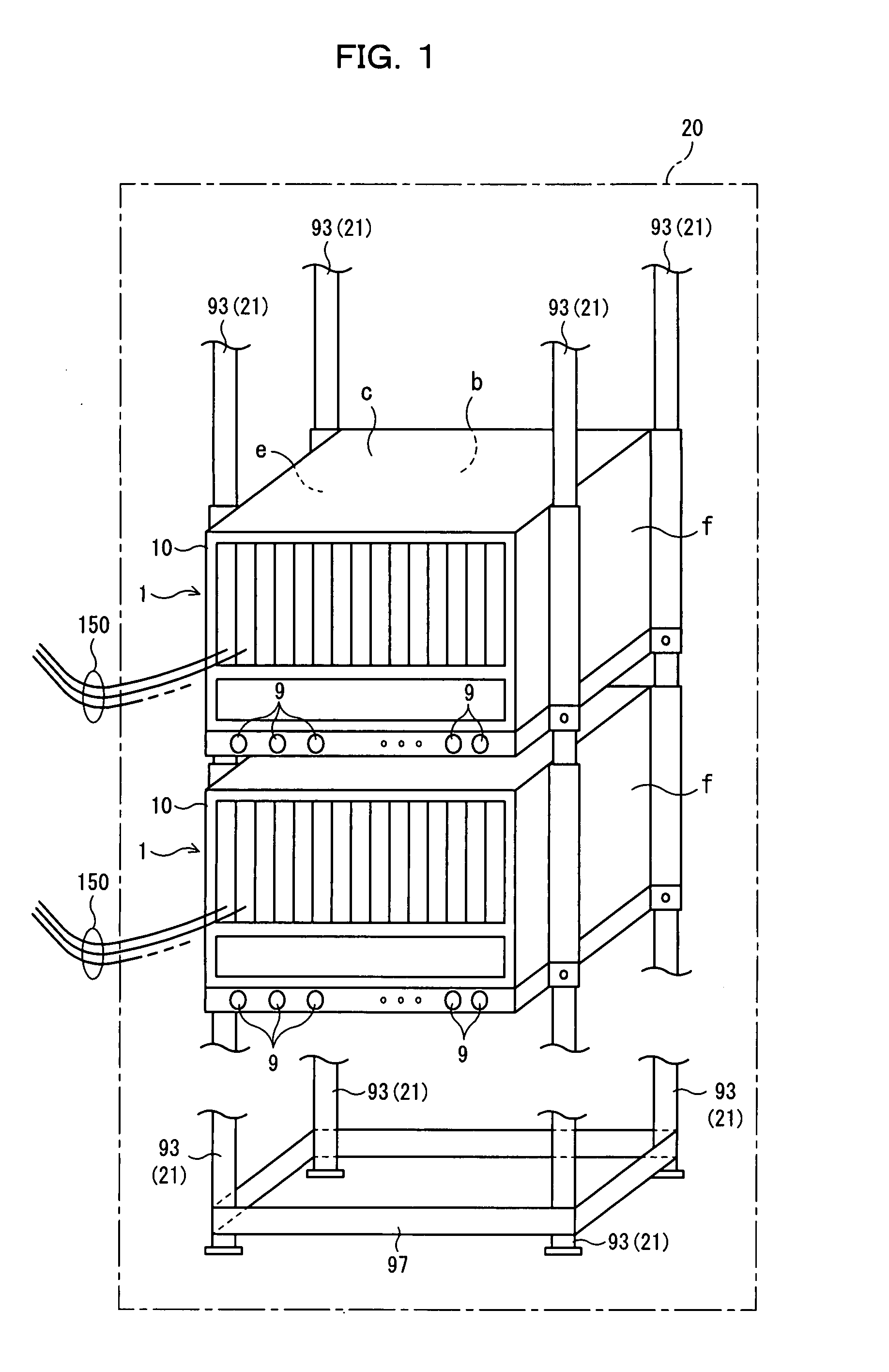
[0067] A structured interface cable connection panel (cable connection interface) (which will hereinafter be referred to simply as a structured panel, unless otherwise specified particularly) in a rack mount apparatus (rack mount type apparatus) to which the present invention is applied is for use in, for example, a communication apparatus (optical transmission apparatus, packet transferring apparatus, line accommodation apparatus, or the like), information processing apparatus, measurement device, and others.

[0068] In a description of a first embodiment, in an optical transmission station, an apparatus in which a plurality of shelves are accommodated in one rack (frame, equipment frame) will be referred to as a rack mount apparatus and an optical cable connected to each of the shelves will be referred to as an interface cable. Moreover, an optical cable will sometimes be referred to as an interface cable or extra c...

second embodiment

[0122] (B) Description of Second Embodiment of the Present Invention

[0123] Furthermore, in a case in which the vertical width of the shelf 1 is long, referring to FIGS. 6 and 7, a description will be given of one example of each of an inserted state of a heat baffle having a cooling function, an installation procedure and a cooling method.

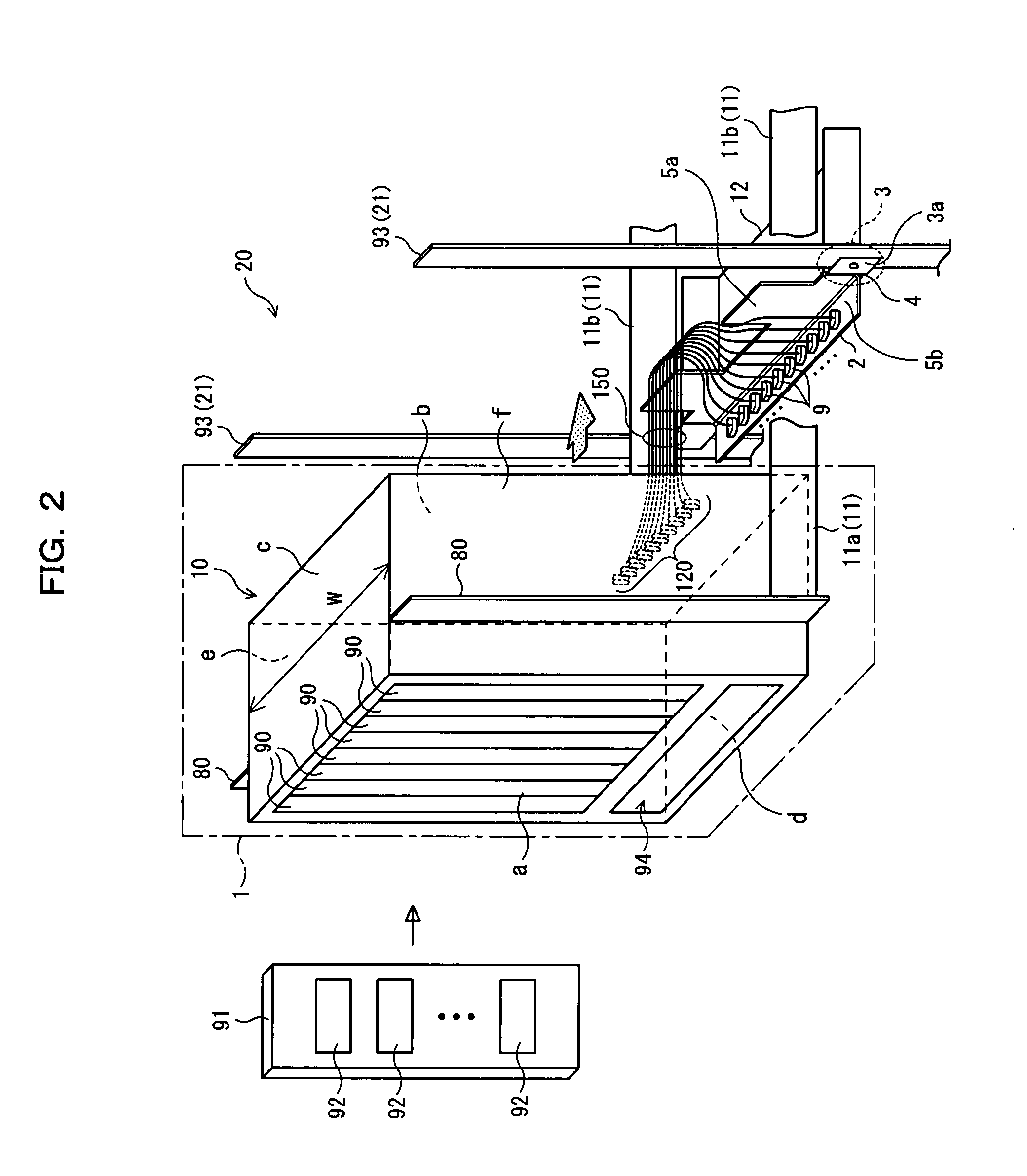
[0124]FIG. 6 is a perspective view showing a shelf with a heat baffle in a rack mount apparatus 20 according to a second embodiment of the present invention. The shelf 1a shown in FIG. 6 is equipped with a suction heat baffle 130, for example, under the opening portion 94 of the front surface a of the shelf 1 shown in FIG. 2 and, for example, three cooling fans 95 for cooling function are accommodated in the opening portion 94 (only one is shown in FIG. 6).

[0125] In this case, since the racks 21 are placed in a closed-up state in a small floor area in the interior of an optical transmission station and a plurality of shelves 1a are mounted in the...

third embodiment

[0141] (C) Description of Third Embodiment of the Present Invention

[0142] Each of the front access panels 2, 2a and 2b in the first and second embodiments is made to fall by the contact with the shelf main body 10 and rotate. In the third embodiment, the worker manually rotates the aforesaid front access panel 2, 2a, 2b so that the front access panel 2, 2a, 2b is accommodated in the rack 21. Each of the front access panels 2a and 2b is made to rotate as well as the front access panel 2, and the description will be given of the front access panel 2 for avoiding the double explanation.

[0143]FIG. 8 is a perspective view for explaining a cable connection state of the front access panel 2 in a rack mount apparatus 20 according to the third embodiment of the present invention, and FIG. 9 is a perspective view for explaining an installation completion state of the front access panel 2 in the rack mount apparatus 20 according to the third embodiment of the present invention. In FIGS. 8 and...


PUM


Abstract

A rack mount apparatus is provided in an optical transmission apparatus. The rack mount apparatus includes a rack, a shelf mounted in the rack and a cross-sectional L-shaped Panel installed in the rack under a device to be rotatable so as to take an opened position and a closed position. This enables not only an easy and reliable connection of an interface cable in the rack mount apparatus without imposing a stress thereon but also a flexible determination or change of a connection position of the interface cable and even considerable improvement of the working efficiency.

Description

CROSS REFERENCE TO RELATED APPLICATION(S) [0001] This application is based on and hereby claims priority to PCT International Application No. PCT / JP2004 / 018299 filed on Dec. 8, 2004, in Japan, the contents of which are hereby incorporated by the reference.BACKGROUND OF THE INVENTION [0002] (1) Field of the Invention [0003] The present invention relates to a cable connection interface for a rack mount type apparatus (rack mount apparatus) for use in, for example, an optical transmission apparatus, communication apparatus, information processing apparatus, measurement device or the like, and to a rack mount apparatus having this cable connection interface. [0004] (2) Description of Related Art [0005] In general, an optical transmission station (optical transmission terminal station, optical repeater station, optical reception terminal station) in an optical transmission network conducts the processing such as amplification, repeating, termination, add-drop or the like with respect to ...

Claims


Application Information

Patent Timeline
IPC IPC(8): H02B1/00
CPCG02B6/4453G02B6/4452
Inventor HOSHINO, YOSHINORIHONGOH, TOMOYUKI
Owner FUJITSU LTD
Why Eureka
Try Eureka