Position and orientation measurement method and position and orientation measurement apparatus

a technology of position and orientation measurement and measurement method, which is applied in the direction of image enhancement, instruments, static indicating devices, etc., can solve the problem of difficulty in following an abrupt change in the velocity or acceleration of a camera

Active Publication Date: 2007-10-18
CANON KK
View PDF8 Cites 61 Cited by
  • Summary
  • Abstract
  • Description
  • Claims
  • Application Information

AI Technical Summary

Benefits of technology

[0021] The present invention has been made in consideration of the above-described problems, and provides a technique of measuring the position and

Problems solved by technology

This is because the position and orientation obtained in each frame contain error whose behavior changes if the combination of input indices changes.
Even in the meth

Method used


Image

  • Position and orientation measurement method and position and orientation measurement apparatus
  • Position and orientation measurement method and position and orientation measurement apparatus
  • Position and orientation measurement method and position and orientation measurement apparatus

Examples


first embodiment

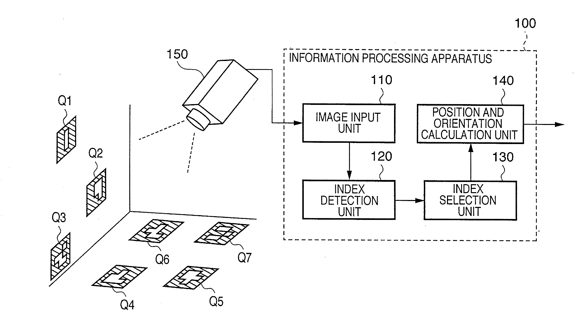
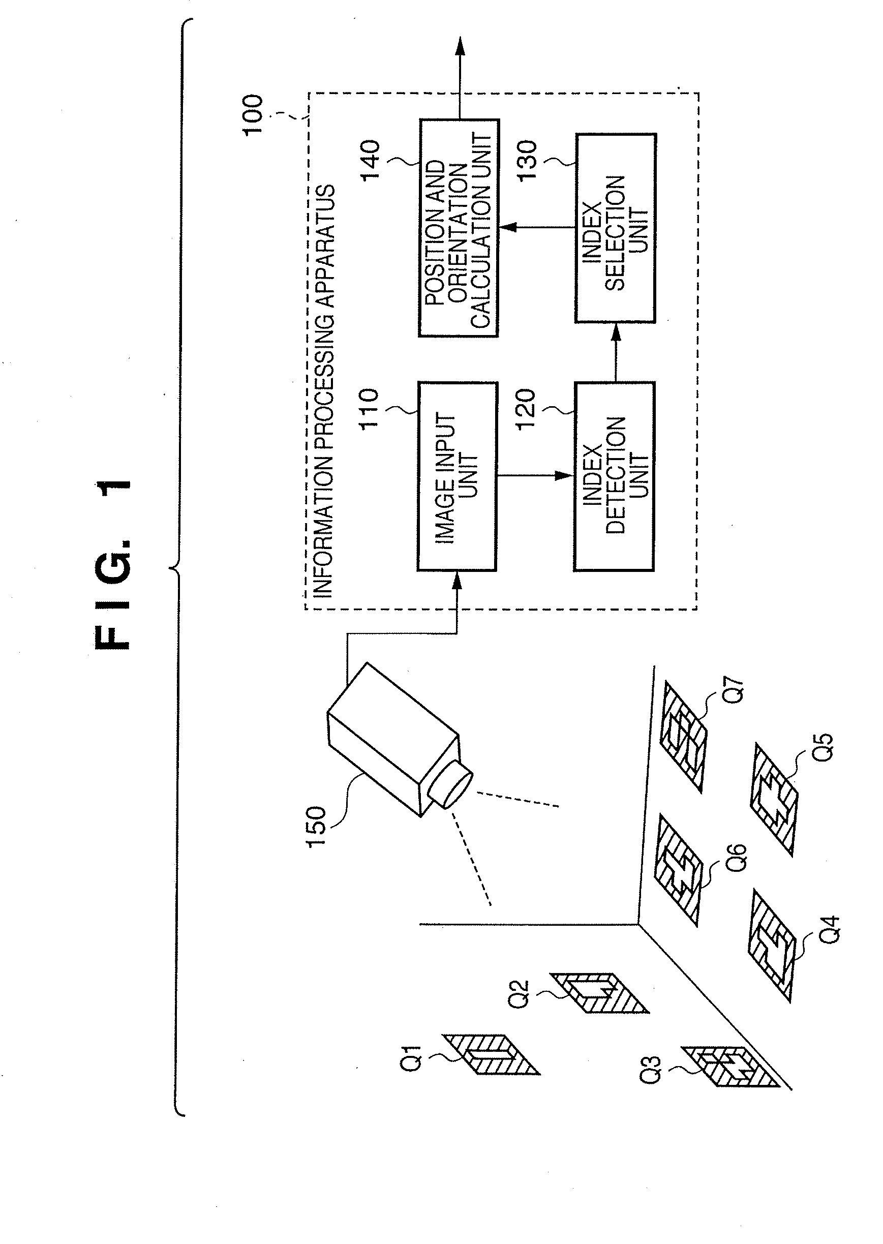
[0088] In this embodiment, the position and orientation of an image sensing device are measured by using a moving image of a physical space sensed by the image sensing device. FIG. 1 is a block diagram showing the functional arrangement of a system for measuring the position and orientation of an image sensing device according to this embodiment. As shown in FIG. 1, the system according to this embodiment includes an image sensing device 150 and an information processing apparatus 100. The information processing apparatus 100 comprises an image input unit 110, index detection unit 120, index selection unit 130, and position and orientation calculation unit 140.

[0089] The environment (physical space) where the system of this embodiment is installed will be described. As shown in FIG. 1, a reference coordinate system which has an origin at a predetermined point and three axes, i.e., x-, y-, and z-axes that cross each other perpendicularly at the origin is defined in the physical spac...

second embodiment

[0173] In this embodiment, the position of a measurement target object is measured by using a plurality of image sensing devices arranged in the physical space. FIG. 7 is a block diagram showing the functional arrangement of a system for measuring the position of a measurement target object by using a plurality of image sensing devices according to this embodiment. As shown in FIG. 7, the system according to this embodiment includes image sensing devices 750a to 750d and an information processing apparatus 700. The information processing apparatus 700 comprises an image input unit 710, index detection unit 720, index selection unit 730, and position calculation unit 740.

[0174] In this embodiment, a measurement target object 760 is used as an example. An index 770 is attached to the measurement target object 760. The information processing apparatus 700 measures the position of the index 770 as the position of the measurement target object 760.

[0175] Each of the image sensing devic...

third embodiment

[0225]

[0226] In the first embodiment, the position and orientation of an image sensing device are measured by using only images sensed by the image sensing device. In other words, a general position and orientation measurement method of measuring a position and orientation by using only images sensed by an image sensing device is improved to enable smooth and accurate measurement, thereby obtaining the position and orientation measurement method of the first embodiment. The same improvement is possible by combining the measurement method of the first embodiment with any method of obtaining a position and orientation by using indices.

[0227]

[0228] Non-patent reference 1 above discloses a method of measuring the position and orientation of an object by using at least one user's view camera attached to the measurement target object and at least one bird's-eye view camera arranged on the ceiling or wall. In this method, an index in the environment is detected from an image captured by t...


PUM


Abstract

The first values of position and orientation of an image sensing device are obtained by using positions of all indices in a frame image. Indices having the same inherent information between a first index group (FIG) in the frame image and a second index group (SIG) in a preceding frame image are detected as a common index. If the information of the SIG contains information different from that of the FIG, second values of the position and orientation are obtained by using the positions of the common indices in the preceding frame image. If the information of the FIG contains information different from that of the SIG, third values of the position and orientation are obtained by using the positions of the common indices in the frame image. The first values are corrected by using correction values based on the obtained first to third values.

Description

BACKGROUND OF THE INVENTION [0001] 1. Field of the Invention [0002] The present invention relates to a technique of obtaining the position and orientation of an image sensing device. [0003] 2. Description of the Related Art [0004] A lot of research has been done in association with mixed reality that presents a text or CG image superimposed on physical space. An image display device to present the mixed reality superimposes an image generated based on the position and orientation of a camera on an image captured by, e.g., a video camera and displays the superimposed image. [0005] To implement such an image display device, it is necessary to measure the relative position and orientation between a camera coordinate system and a reference coordinate system defined in physical space. An example will be considered here, in which a virtual object is superimposed at a predetermined position, i.e., in a room or on a table in the physical environment. In this case, the reference coordinate s...

Claims


Application Information

Patent Timeline
IPC IPC(8): G06K9/36
CPCG06T7/0042G06T7/2033G06T2207/30244G06T2207/30241G06T2207/10016G06T7/73G06T7/246
Inventor SATOH, KIYOHIDEARATANI, SHINICHIUCHIYAMA, SHINJIMORITA, KENJITAKEMOTO, RIKA
Owner CANON KK
Why Eureka
Try Eureka