Disposable Chamber for Analyzing Biologic Fluids

a technology of biologic fluids and chambers, which is applied in the field of chambers for analyzing biologic fluids, can solve the problems of difficult mold accuracy, large limitations of the counting chamber formed from rigid upper and lower panels separated by rigid particles, and relatively high cost of the hemocytometer chamber. , to achieve the effect of providing the desired accuracy, reducing the cost of manufacturing, and ensuring the accuracy of the measuremen

Active Publication Date: 2007-10-18
WARDLAW PARTNERS +2
View PDF28 Cites 199 Cited by
  • Summary
  • Abstract
  • Description
  • Claims
  • Application Information

AI Technical Summary

Benefits of technology

[0014] An advantage of the present invention is, therefore, that a chamber is formed having a volume that is accurately determinable because the height of the chamber is substantially uniform.
[0015] Another advantage of the present invention is that it can be manufactured in an inexpensive form and still provide the desired accuracy. The present invention does not require accurately machined voids or separators to accurately establish volume. Consequently, the invention can be manufactured inexpensively and still provide the desired accuracy. In addition, because it can be manufactured inexpensively, the present invention can practically be offered in a disposable form.

Problems solved by technology

Because they are precisely manufactured, hemocytometer chambers are relatively expensive and were not considered disposable.
Modern precision plastics molding techniques have allowed the manufacture of some types of hemocytometer chambers at sufficiently low cost so as to be considered disposable in some instances, but chambers requiring substantial precision and / or thicknesses less than the traditional 0.1 mm are very difficult to mold accurately.
A counting chamber formed from rigid upper and lower panels separated by rigid particles has substantial limitations, however.
The differences in bead diameter is a problem because while it is easy to determine and / or control the mean diameter of the beads, the spread of diameters is less well controlled, rendering the system less accurate than is desired.
A greater problem is the presence of particulate debris as shown in FIG. 2.
The debris 8 can “prop up” the coverslip 4 and create a large area of increased volume in the chamber, which destroys its accuracy.
Another issue with this type of prior art chamber is that it is difficult to package a plurality of such disposables in an instrument used for automatically scanning and counting particles, such as an image analyzing system.

Method used


Image

  • Disposable Chamber for Analyzing Biologic Fluids
  • Disposable Chamber for Analyzing Biologic Fluids
  • Disposable Chamber for Analyzing Biologic Fluids

Examples


Embodiment Construction

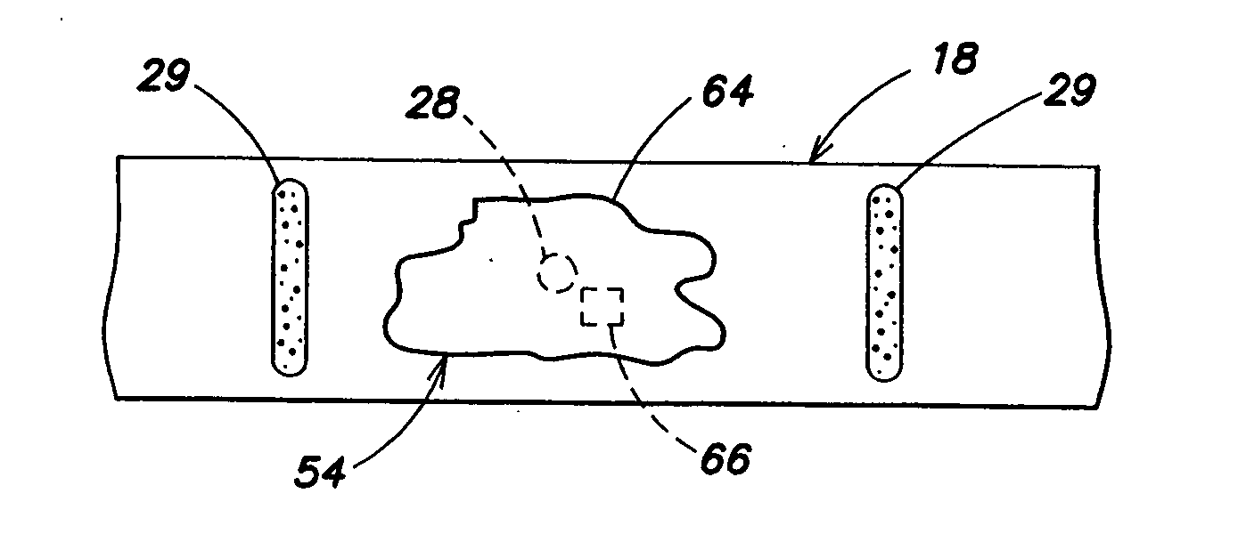
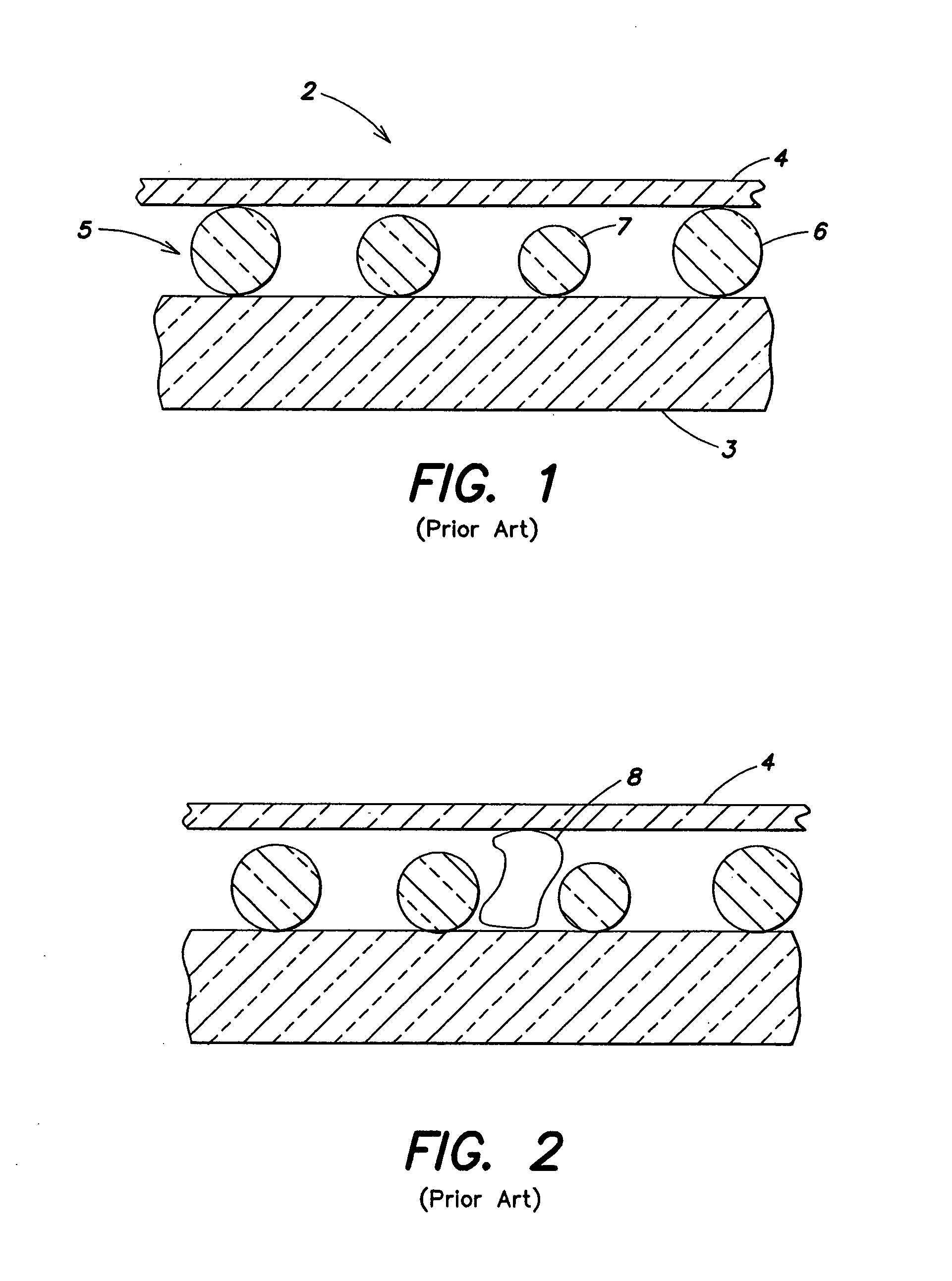
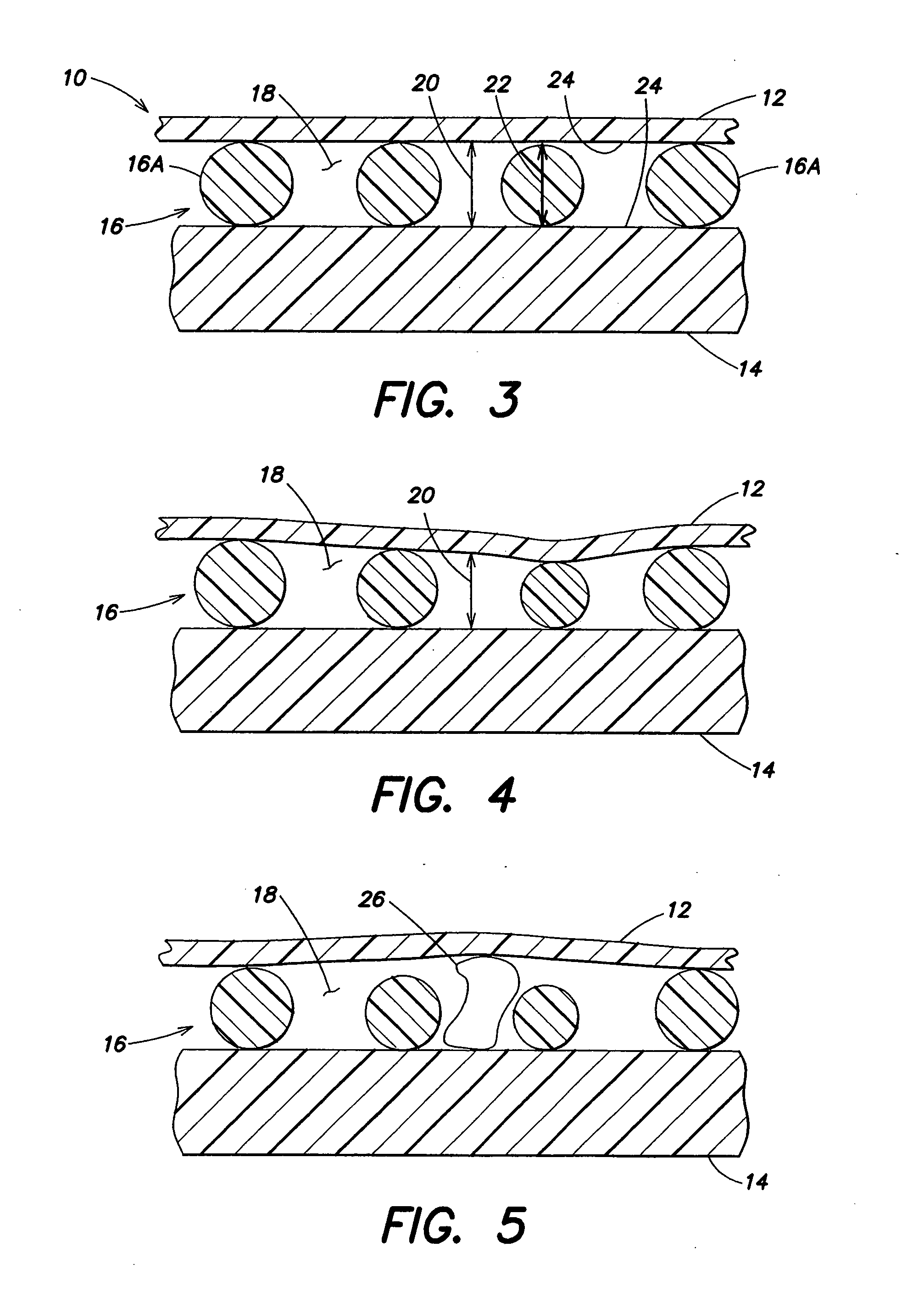
[0030] Referring to FIGS. 3-11, the present invention apparatus 10 for analyzing biologic fluid includes a first planar member 12, a second planar member 14, and at least three separators 16. At least one of planar members 12, 14 is transparent. The separators 16 are disposed between the members 12, 14, and separate the planar members 12, 14 to form a chamber 18 having a height 20. At least one of the members 12, 14 or separators 16 is sufficiently flexible to permit the chamber height 20 between the members 12, 14 to approximate the mean height of the separators 16.

[0031] The separators 16 can be any structure that is disposable between the planar members 12, 14, operable to space the planar members 12, 14 apart from one another. The dimension of a separator 16 that extends between the planar members is referred to herein as the height 22 of the separator 16. The heights 22 of the separators 16 typically do not equal one another exactly, but are within commercially acceptable tole...


PUM

PropertyMeasurementUnit
thicknessesaaaaaaaaaa
chamber heightsaaaaaaaaaa
diameteraaaaaaaaaa

Abstract

An apparatus for analyzing biologic fluid is provided that includes a first planar member, a second planar member, and at least three separators. At least one of planar members is transparent. The separators are disposed between the members, and separate the members to form a chamber having a height. At least one of the members or separators is sufficiently flexible to permit the chamber height to approximate the mean size of the separators. During use, the biologic fluid to be analyzed is disposed within the chamber.

Description

BACKGROUND OF THE INVENTION [0001] 1. Technical Field [0002] The present invention relates to chambers for analyzing biologic fluids in general, and to chambers that permit the enumeration of particulate matter within the biologic fluid in particular. [0003] 2. Background Information [0004] The classic method of enumerating particles in a liquid medium, such as blood cells in whole blood or bacteria or other material in urine or other biologic fluid is the hemocytometer, which includes a chamber manufactured to a precise height and having visible ruled areas of precise dimension. The liquid containing the particles to be enumerated is introduced into the chamber. The liquid is diluted if necessary to reduce the number of particles to a manageable number. The operator then counts the number of particles in a given demarcated area. Since the area and height of the chamber are precisely known, the particle count per volume can be calculated. Although these chambers are generally ruled ...

Claims


Application Information

Patent Timeline
Patent Type & Authority Applications(United States)
IPC IPC(8): B01D11/04C12M1/34C12M1/40G01N1/31G01N15/14
CPCB01L3/5027G01N2021/0346B01L2200/025B01L2200/12B01L2300/0877B01L2300/0887B01L2400/0406G01N1/2813G01N1/312G01N21/03G01N35/00009G01N2015/008G01N2015/1006G01N2015/1486G01N2021/0364Y10T436/101666Y10T436/25375B01L3/502738G01N33/48764G01N33/492G01N1/36G02B21/34
Inventor WARDLAW, STEPHEN C.
Owner WARDLAW PARTNERS
Why Eureka
Try Eureka