System and method for managing the operation of a battery powered surgical tool and the battery used to power the tool

a technology for surgical tools and batteries, applied in the field of battery powered surgical tools, can solve the problems of not providing information if, and not providing a complete measure of the health of the battery

Inactive Publication Date: 2007-10-18
STRYKER CORP
View PDF11 Cites 1250 Cited by
  • Summary
  • Abstract
  • Description
  • Claims
  • Application Information

AI Technical Summary

Benefits of technology

[0018] Often these data are made available through a communications bus to a device monitor, also part of the system of this invention. The device monitor includes a processor. The device monitor processor evaluates the received data to determine the operating states of both the tool and the battery. If these evaluations indicat

Problems solved by technology

The repetitive exposure to this environment causes a battery cells' ability to store electric charge to degrade.
Unfortunately, this information alone does not provide a complete measure of the battery state of health.
For example, this information alone does not provide information if the stored energy is sufficient to power the device to which the battery is attached for the time required to perform the surgical procedure.
This means that, during the performance of a procedure, if the battery's stored energy appreciably depletes, the procedure is interrupted to replace the battery.
This increases the overall time takes to perform the procedure.
A console may be configured to take this action if the entry of the tool into the out of boundary state could result in the potential of injury.
There is no ready means to determine if the tool is in/approaching an outer of boundary state that can result in tool malfunction.
This m

Method used


Image

  • System and method for managing the operation of a battery powered surgical tool and the battery used to power the tool
  • System and method for managing the operation of a battery powered surgical tool and the battery used to power the tool
  • System and method for managing the operation of a battery powered surgical tool and the battery used to power the tool

Examples


Embodiment Construction

I. Overview

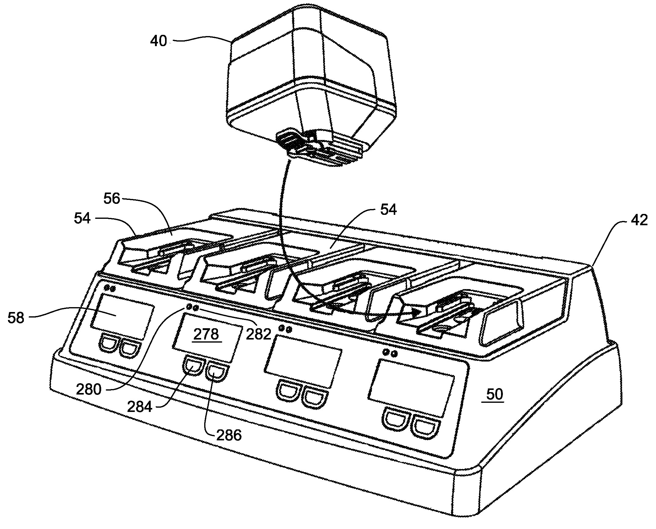
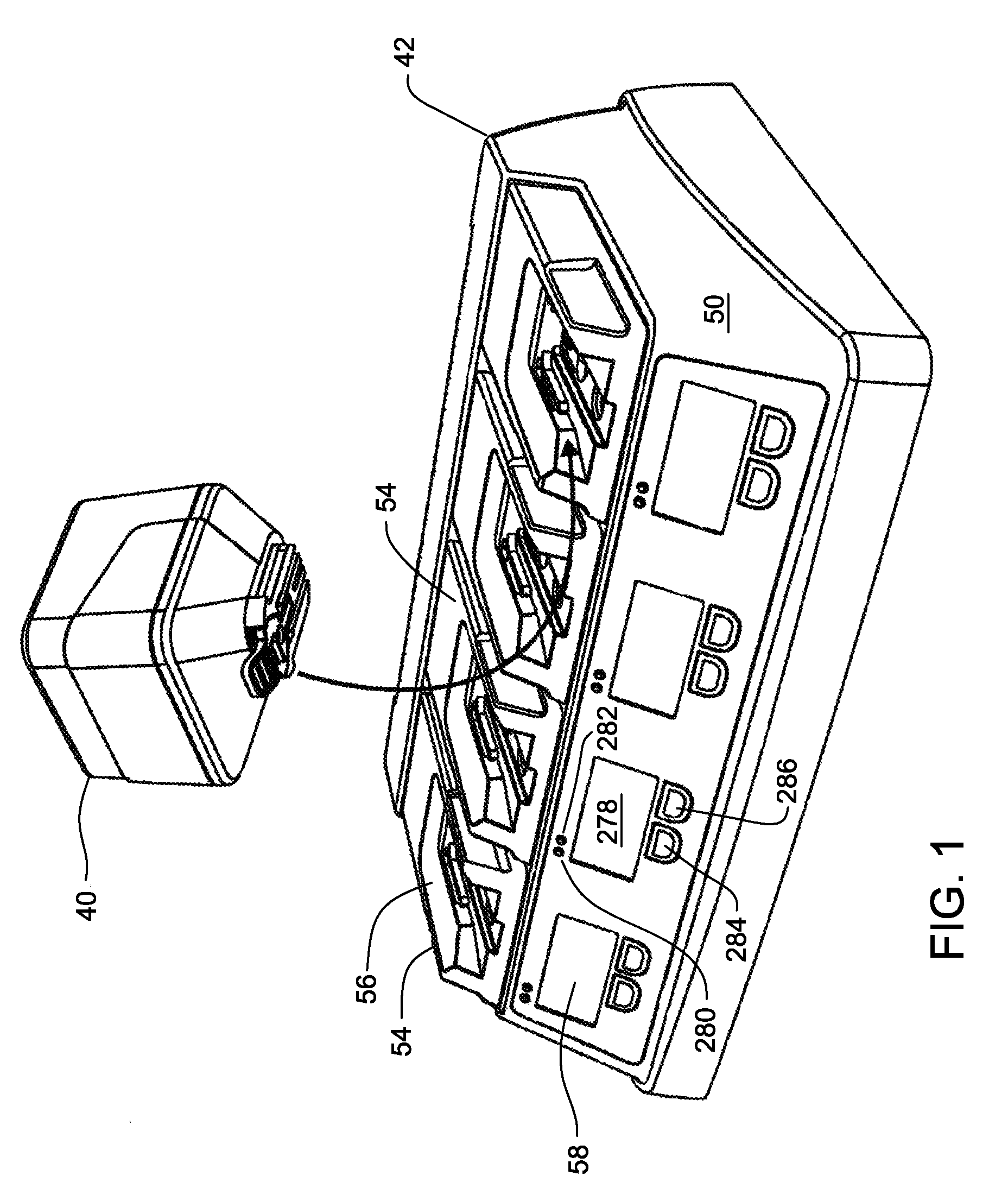
[0057]FIG. 1 illustrates a battery 40 and battery charger 42 constructed in accordance with this invention. Battery 40, includes a set of rechargeable cells 44 (FIG. 3) a microcontroller 46 and a temperature sensor 48 (FIG. 12). Battery charger 42 includes a housing 50 with a number of pockets 52 (FIG. 20). Each pocket 52 removably receives a module 54 associated with a specific type of battery. The module 54 is shaped to define a complementary socket 56 for receiving the head end of the associated battery 40. Internal to the battery charger 42 are components for reading the data stored in the battery microcontroller 46 and for charging the battery cells 44. A plurality of I / O units 58 are attached to the charger 42. Each I / O unit 58 functions as the sub-assembly through which instructions are entered and charge state information presented about an individual one of the batteries 40 attached to the charger 42.

II. Battery And Method of Battery Assembly

[0058] As seen in F...


PUM

PropertyMeasurementUnit
Timeaaaaaaaaaa
Speedaaaaaaaaaa

Abstract

A surgical power tool system including a cordless powered surgical tool, a battery for energizing the tool and a charger for charging the battery. The battery includes a memory. When the battery is attached to the tool, a processor integral with the tool writes data to the memory regarding the operation of the tool. When the battery is attached to the charger, the data are read out the battery memory. These data are then evaluated to determine the operational state of the tool.

Description

RELATIONSHIP TO EARLIER FILED APPLICATIONS [0001] This application is a continuation-in-part based on U.S. patent application Ser. No. 11 / 551,335 filed 20 Oct. 2006 which claims priority under 35 U.S.C. Sec 119 from U.S. Provisional Patent App. No. 60 / 729,338 filed 21 Oct. 2005.FIELD OF THE INVENTION [0002] This invention is related to battery powered surgical tools. More particularly, this invention is related to system for managing these tools and the batteries used to power them, based on data contained in the batteries BACKGROUND OF THE INVENTION [0003] A battery often energizes a powered surgical tool used in an operating room to perform a surgical procedure. The use of a battery eliminates the need to provide a power cord connected to an external power source. The elimination of the power cord offers several benefits over corded surgical tools. Surgical personnel using this type of tool do not have to concern themselves with either sterilizing a cord so that it can be brought ...

Claims


Application Information

Patent Timeline
IPC IPC(8): A61B17/00H02J7/00
CPCH01M10/42H01M10/425H02J7/0004H01M10/48H01M10/46B29L2031/3481B29K2995/0027B29L2031/7546B29C65/1616B29C65/1635B29C65/1677B29C65/7829B29C66/1162B29C66/1282B29C66/1284B29C66/12841B29C66/1286B29C66/322B29C66/542B29C66/71B29C66/8322H02J7/00036H02J7/00047Y02E60/10B29K2081/04
Inventor MALACKOWSKI, DON
Owner STRYKER CORP
Why Eureka
Try Eureka