
System for conditioning surfaces in vivo

Active Publication Date: 2007-10-18
MEDTRONIC PS MEDICAL
View PDF29 Cites 4 Cited by
  • Summary
  • Abstract
  • Description
  • Claims
  • Application Information

AI Technical Summary

Benefits of technology

[0012] In another embodiment, a method for inhibiting blood platelet adhesion to a surface in vivo includes applying electrical energy to the surface, with the electrical energy being derived from an electropositive current providing an electropositive current density of between about 0.001 and about 1

Problems solved by technology

Many surfaces in the human body that are exposed to blood flow are at risk of blood component deposit formation thereon.
Deposit formation on surfaces located at areas of the body which are critical to blood transmission can be detrimental or even hazardous to the person's health.
For example, deposit formation on heart valves, veins, and arteries can restrict the flow of blood therethrough and / or reduce the functionality thereof.
As a result, deposit formation can lead to obstructed blood flow through at least portions of the body, which limited blood flow can have serious negative implications on the health of the person.
In some cases, thrombosis is believed to be caused by turbulence in the blood stream, with such turbulence causing relatively forceful impact among red blood cells that causes damage to the cells, and ultimately proneness to adhere to surfaces.
Some medical devices, however, have been found to be particularly susceptible to thrombogenesis.
Current anti-coagulative drug therapy is far from ideal.
Each patient with an implanted heart valve not only carries a risk for valve thrombosis or systemic emboli, but also a risk of bleeding which follows anti-coagulant therapy.

Method used


Image

  • System for conditioning surfaces in vivo
  • System for conditioning surfaces in vivo
  • System for conditioning surfaces in vivo

Examples


example i

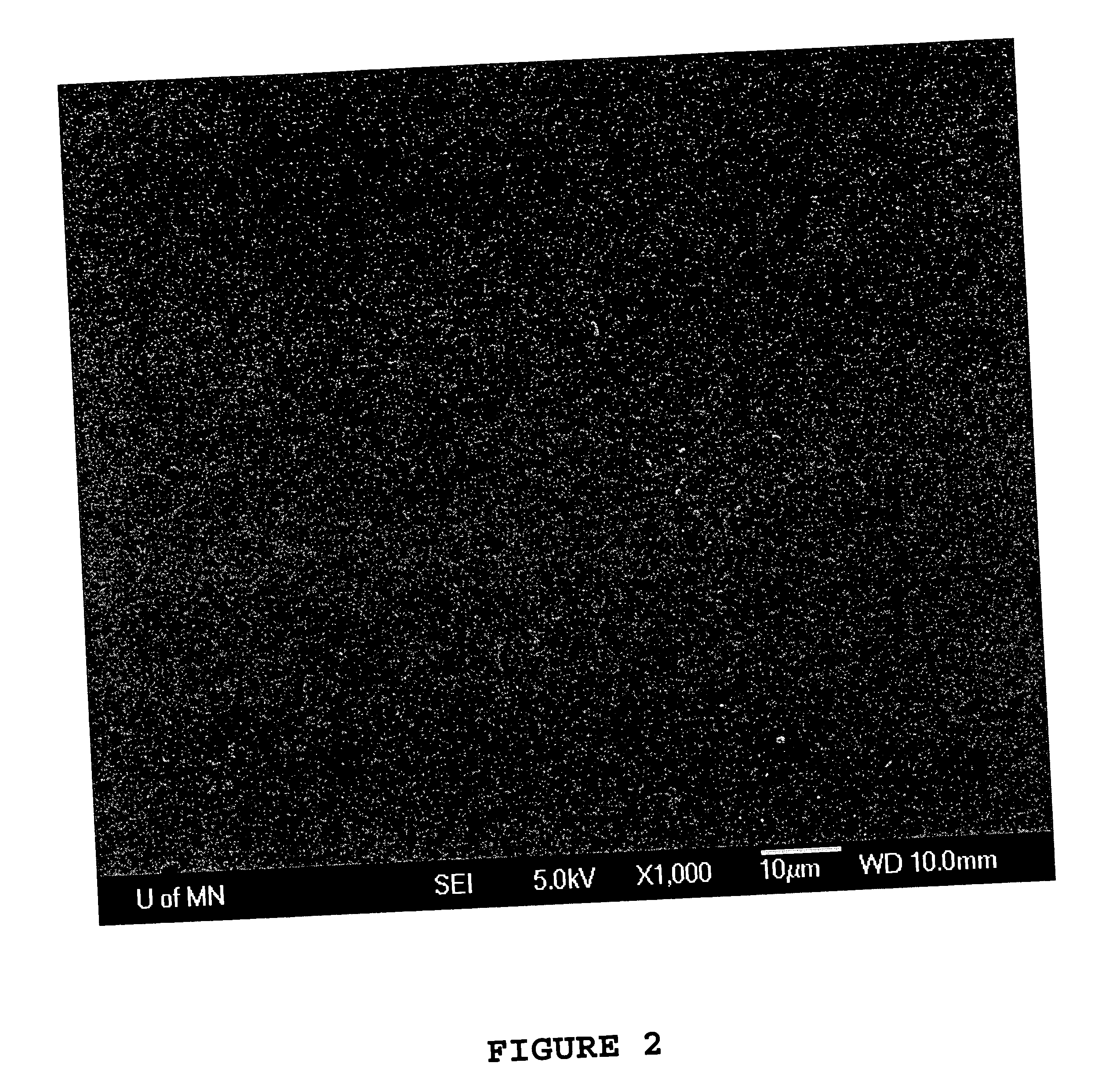
[0029] A pyrolytic carbon aortic valve assembly similar to that utilized in the control was cleaned as described with reference to the control procedure. The pyrolytic carbon valve assembly was exposed to a first 200 ml aliquot of a human blood sample for 45 min. at 37° C. in a pulsatile blood perfusion system. The blood perfusion system was arranged with an approximate output of 5 L per min. The valve leaflets of the assembly were oriented in the blood perfusion system with their respective major planes disposed parallel to axial blood flow through the system. Subsequent to the exposure to the human blood, the pyrolytic carbon valve assembly was removed from the system, rinsed in saline, and inspected under scanning electron microscope at a magnification of 1,000×, with an image from such inspection being shown in FIG. 3. The image illustrates completely confluent blood platelet adhesion.

example ii

[0030] A pyrolytic carbon valve assembly similar to those utilized in the control and in Example I was cleaned through the protocol identified in the control. The cleaned pyrolytic carbon valve assembly was exposed to a second 200 mL aliquot of the human blood sample for 45 min. at 37° C. in a pulsatile blood perfusion system. The blood perfusion system was set up with an approximate output of 5 L per min. An electrical lead was electrically connected to the valve assembly carrying a current of 3.0 mA to create electropositive current density of 0.24 mA / cm2 at the valve assembly. The current was delivered as a pulsed square waveform having a 25 ms duration pulse at 20 Hz. The valve leaflets were axially oriented in the blood perfusion system, such that the major planes of the respective valve leaflets were parallel to the direction of blood flow.

[0031] Upon completion of 45 min. of exposure to the blood perfusion system, the valve assembly was removed from the system, rinsed in sal...


PUM


Abstract

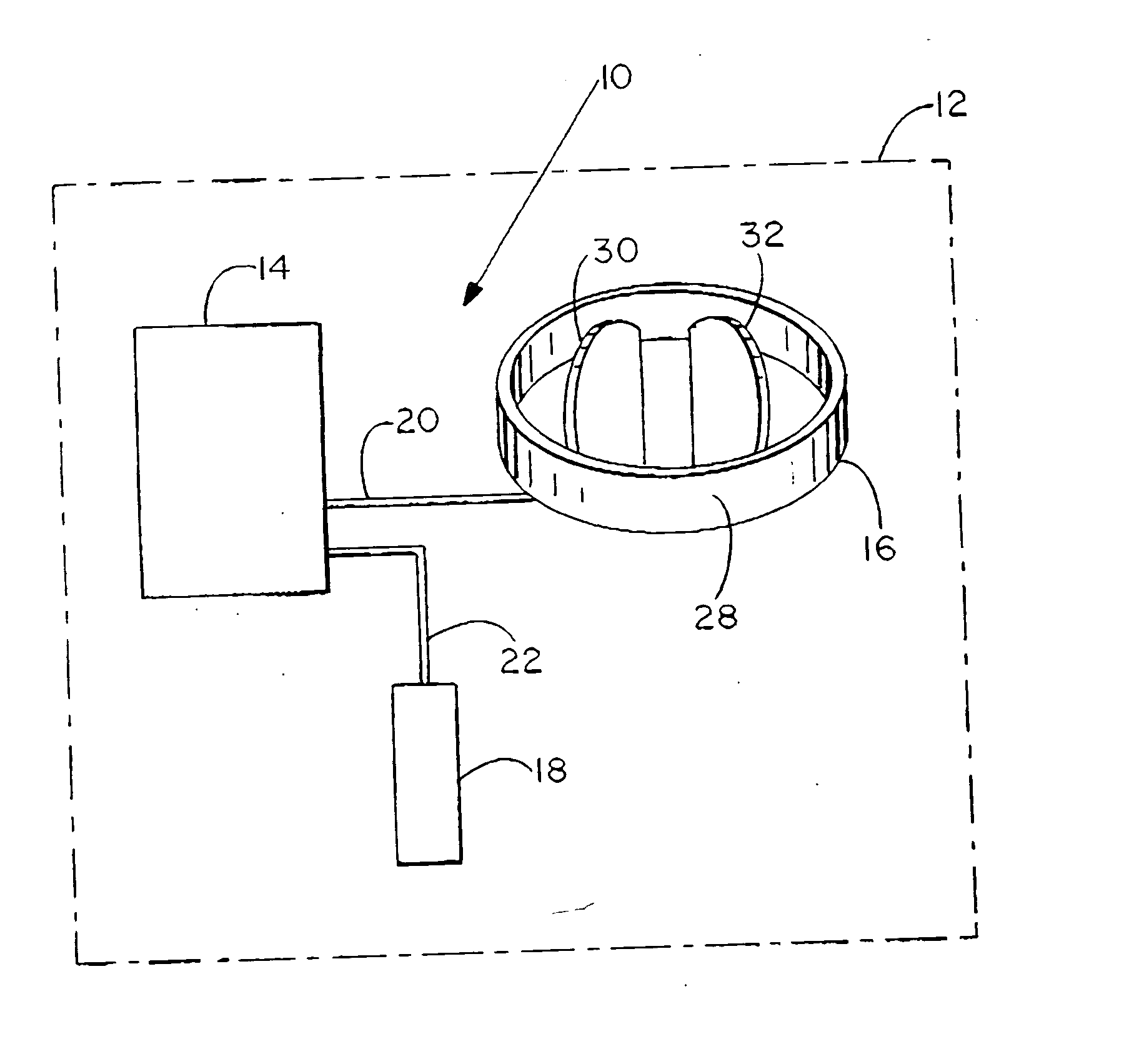
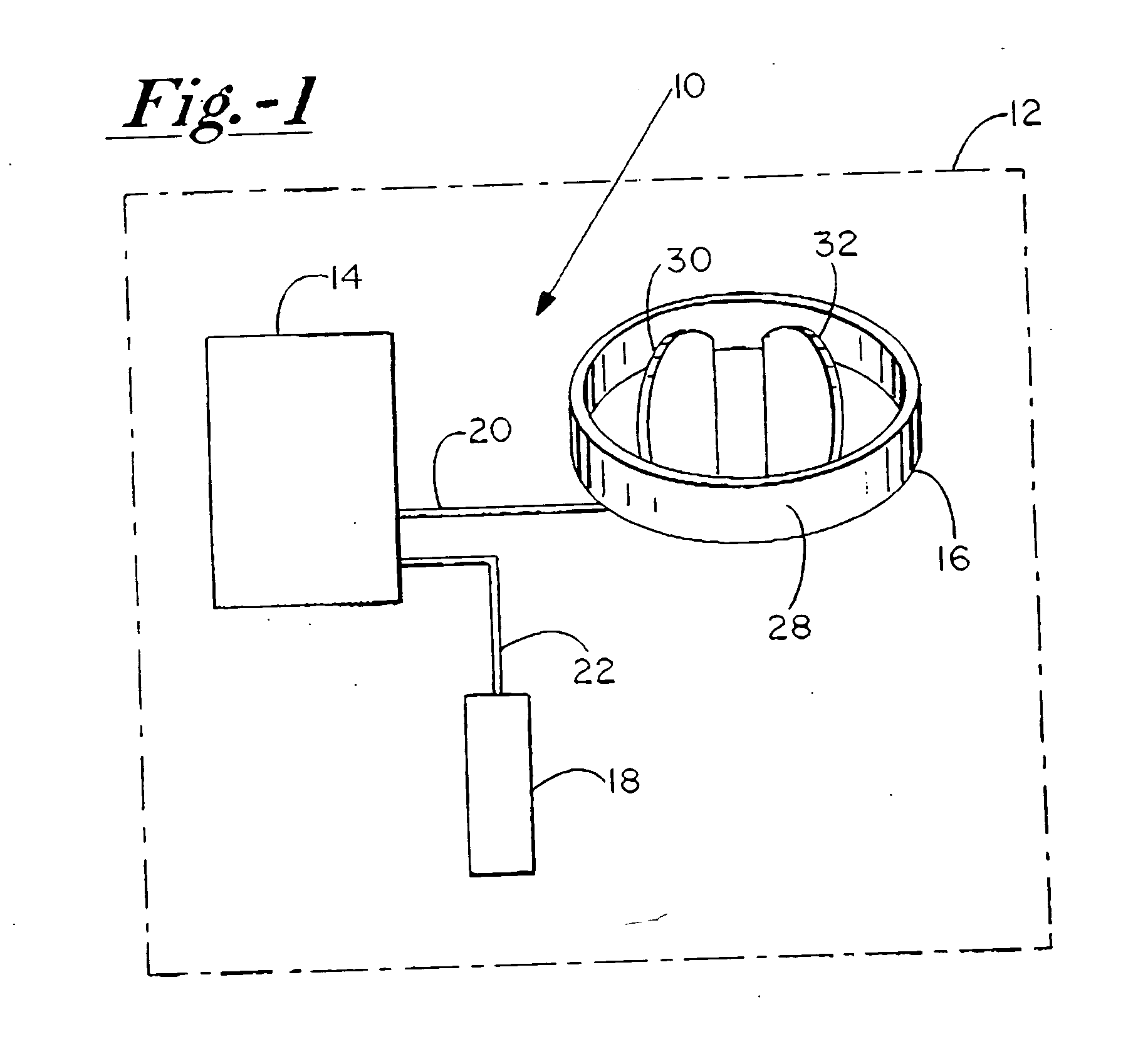
A system and method for conditioning surfaces of a body in vivo includes providing an electrical energy source, coupling the electric energy source to the surface, and delivering electropositive current from the electrical energy source to the surface so as to generate a sub-threshold current density on the surface. In preferred embodiments, the sub-threshold electropositive current density is between about 0.001 and about 1.0 mA / cm2.

Description

FIELD OF THE INVENTION [0001] The present invention relates to systems and methods for conditioning various surfaces in vivo generally, and more particularly to systems and methods for inhibiting blood platelet adhesion on such surfaces, and specifically blood platelet adhesion to surfaces of implanted medical devices. BACKGROUND OF THE INVENTION [0002] Many surfaces in the human body that are exposed to blood flow are at risk of blood component deposit formation thereon. Such deposits can include, for example, blood platelets, fibrinogen, minerals such as calcium, and the like. Deposit formation on surfaces located at areas of the body which are critical to blood transmission can be detrimental or even hazardous to the person's health. For example, deposit formation on heart valves, veins, and arteries can restrict the flow of blood therethrough and / or reduce the functionality thereof. As a result, deposit formation can lead to obstructed blood flow through at least portions of the...

Claims


Application Information

Patent Timeline
IPC IPC(8): A61N1/00
CPCA61N1/20
Inventor PEDERSON, BRIAN D.
Owner MEDTRONIC PS MEDICAL
Learn More