Trialing system and method for modular hip joint replacement system

a hip joint replacement and modular technology, applied in the field of system and method for trialing components of modular hip prosthesis, can solve the problems of unfulfilled need, one-piece prosthesis, and difficulty in precise positioning of the upper portion and hence the head of the prosthesis, and achieve the effect of accurate approximation

Inactive Publication Date: 2007-10-18
DEPUY PROD INC
View PDF98 Cites 34 Cited by
  • Summary
  • Abstract
  • Description
  • Claims
  • Application Information

AI Technical Summary

Benefits of technology

[0024] The distal stem component can also include opposite flats defined at the proximal portion of the component. These opposite flats can engage complementary internal flats of a second component of the proximal trial body assembly to essentially rotationally lock the component to the distal stem component. Thus, this second component does not rotate relative to the distal stem portion once the proximal trial body assembly has been mounted on the stem component. The trial body assembly can include a third component that is configured to engage the sleeve component of the final implant assembly. This third component is mounted for rotation about the second component to facilitate integration of the proximal trial body assembly with the distal stem and sleeve components.
[0026] The proximal trial body assembly also includes a second component defining a second bore configured for mounting the second component on the distal stem component with the proximal portion of the distal stem component extending through the bore. An interdigitating engagement is defined between the first and second components for fixing the first component to the second component after the first component has been rotated relative to the distal stem component. The interdigitating engagement can preferably be in the form of complementary radially splined surfaces. The interdigitating engagement can permit relative rotation between the two components while the anteversion angle is being determined. The splines can generate an audible “click” at angular increments as the first component is rotated.
[0028] One significant benefit of the present invention is that the true anteversion rotational angle of the femur can be determined and accurately approximated in a final hip replacement implant. Another benefit is that certain implant components of the final implant can be used to perform the trialing procedure so no errors arise due to non-conformity of the trial component relative to the implant component.
[0029] Another benefit presented by the invention is that the anteversion angle can be determined without requiring external referencing, such as by x-ray. In addition, the invention eliminates the necessity for performing angular measurements and then duplicating these measurements during the construction of the final implant.

Problems solved by technology

Such a need for prostheses of varying shapes and sizes can create a number of problems in regard to use of a one-piece prosthesis.
Moreover, since the bow of the stem must conform to the bow of the intramedullary canal of the patient's femur, rotational positioning of the upper portion (i.e. proximal end) of the prosthesis is limited thereby rendering precise locating of the upper portion and hence the head of the prosthesis very difficult.
Such a design allows the distal stem component to be selected and thereafter implanted in the patient's bone in a position which conforms to the patient's anatomy while also allowing for a limited degree of independent positioning of the proximal neck component relative to the patient's pelvis.
However, there remains an unfulfilled need for a trialing system (as well as a modular implant system) that is able to accurately reproduce the anteversion angle of the femur.
The problem of ensuring proper anteversion alignment is exacerbated where the modular system includes a curved distal stem.
Obviously, a curved stem means that the rotational alignment cannot be modified by simply rotating the stem within the prepared bore, since the bore itself is also curved.
At present no modular implant or modular trial system is available that allows for accurate reproduction of the anteversion rotational orientation.

Method used


Image

  • Trialing system and method for modular hip joint replacement system
  • Trialing system and method for modular hip joint replacement system
  • Trialing system and method for modular hip joint replacement system

Examples


Embodiment Construction

[0049] While the invention is susceptible to various modifications and alternative forms, a specific embodiment thereof has been shown by way of example in the drawings and will herein be described in detail. It should be understood, however, that there is no intent to limit the invention to the particular form disclosed, but on the contrary, the intention is to cover all modifications, equivalents, and alternatives falling within the spirit and scope of the invention as defined by the appended claims.

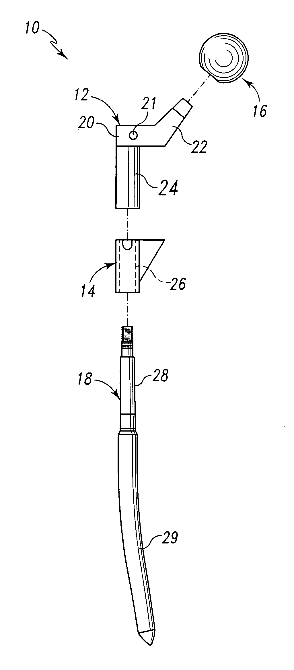
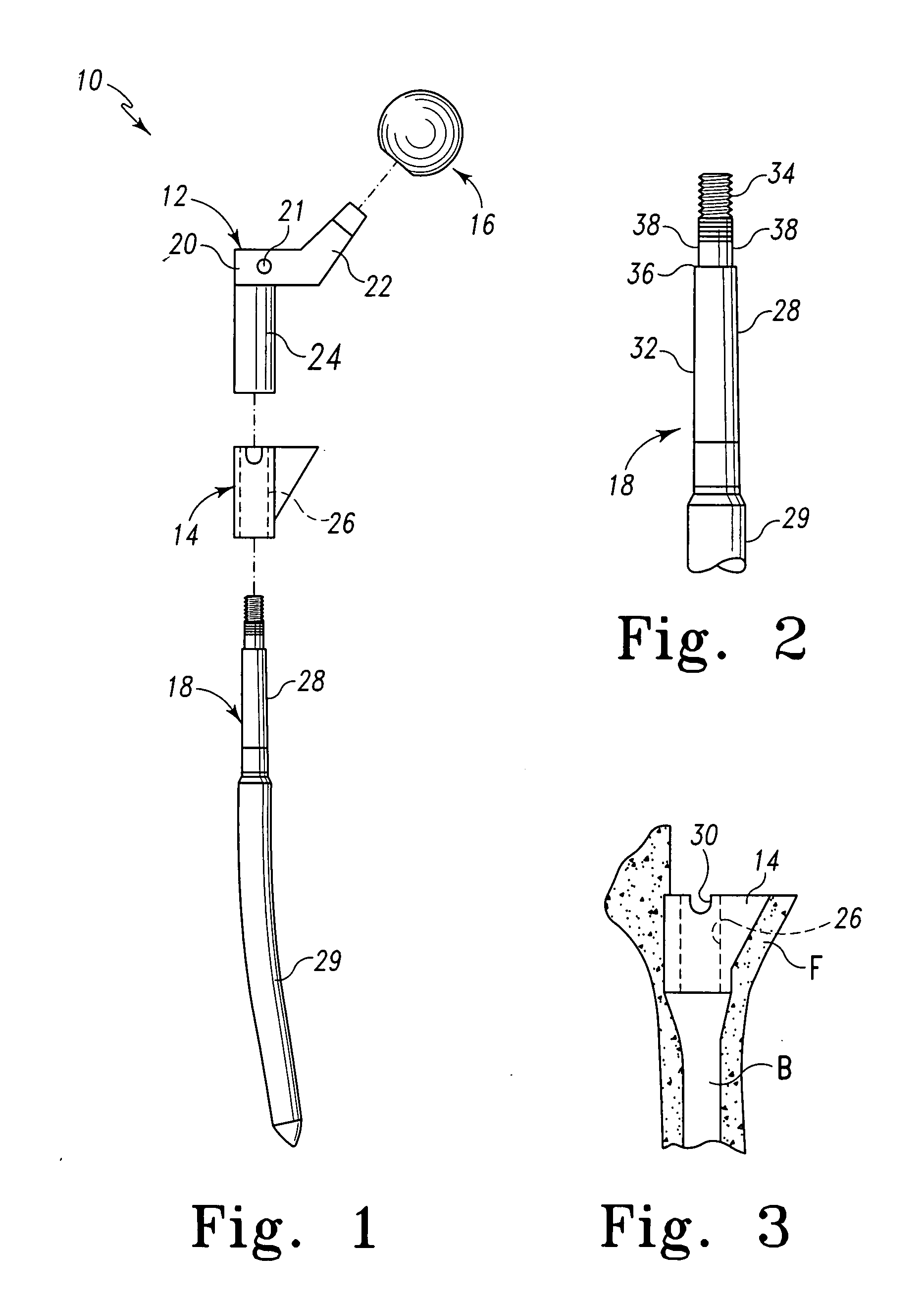
[0050] Referring now to FIGS. 1-3, there is shown a modular prosthesis 10 for use during performance of a joint replacement procedure such as a hip replacement procedure. It should be appreciated that although the present invention is herein exemplarily described in regard to performance of a hip replacement procedure, the concepts of the present invention may be utilized in regard to replacement procedures at numerous other joint locations throughout the body. For example, the concep...


PUM


Abstract

A system and method for trialing a modular hip replacement system (10) permits evaluation and replication of the anatomic anteversion rotational angle of the femur. A distal stem component (18) of the hip replacement system (10) includes a proximal portion (34) having a locator feature (35) that is externally accessible when the stem component is mounted within the femur. A proximal trial body assembly (60) is mounted on the proximal portion (34) of the distal stem component (18) to permit rotation of a trial neck component (62). The trial neck component (62) also includes a locator feature (126) that can be externally referenced to determine the anteversion angle.

Description

[0001] This application is a continuation of co-pending application Ser. No. 10 / 327,488, filed on Dec. 20, 2002 (Patent Application Publication No. U.S. 2004 / 0122525. The disclosure of the above-identified published patent application is hereby totally incorporated by reference in its entirety.CROSS-REFERENCE TO RELATED APPLICATIONS [0002] Cross reference is made to the following applications: U.S. application Ser. No. 10 / 327,187, filed on Dec. 20, 2002 which is entitled “ADJUSTABLE BIOMECHANICAL TEMPLATING & RESECTION INSTRUMENT AND ASSOCIATED METHOD”, U.S. application Ser. No. 10 / 327,196, filed on Dec. 20, 2002 (now U.S. Pat. No. 7,022,141) which is entitled “ALIGNMENT DEVICE FOR MODULAR IMPLANTS AND METHOD”, and U.S. application Ser. No. 10 / 327,527, filed on Dec. 20, 2002 which is entitled “INSTRUMENT AND ASSOCIATED METHOD OF TRIALING FOR MODULAR HIP STEMS”. The disclosures of each of the above-identified patent applications and patent(s) are hereby totally incorporated by refere...

Claims


Application Information

Patent Timeline
Patent Type & Authority Applications(United States)
IPC IPC(8): A61F2/32A61B17/58A61F2/00A61F2/30A61F2/36A61F2/38A61F2/40A61F2/46
CPCA61F2/36A61F2250/0087A61F2/3676A61F2/38A61F2/40A61F2/4684A61F2002/30332A61F2002/30354A61F2002/30512A61F2002/30604A61F2002/30616A61F2002/30713A61F2002/30738A61F2002/30886A61F2002/3611A61F2002/3625A61F2002/365A61F2002/3674A61F2002/3686A61F2220/0025A61F2220/0033A61F2250/006A61F2250/0064A61F2/367A61F2002/30507A61F2002/3071
Inventor DANIELS, DAVID W.DWYER, KIMBERLY A.MATTINGLY, DAVID
Owner DEPUY PROD INC
Why Eureka
Try Eureka