

Process for superheated steam
a technology of superheated steam and process, which is applied in the direction of combustible gas catalytic treatment, sustainable manufacturing/processing, lighting and heating apparatus, etc., can solve the problems of deficiency of superheated steam and excessive high pressure steam
- Summary
- Abstract
- Description
- Claims
- Application Information
AI Technical Summary
Benefits of technology
Problems solved by technology
Method used
Image

Examples
examples 1-5
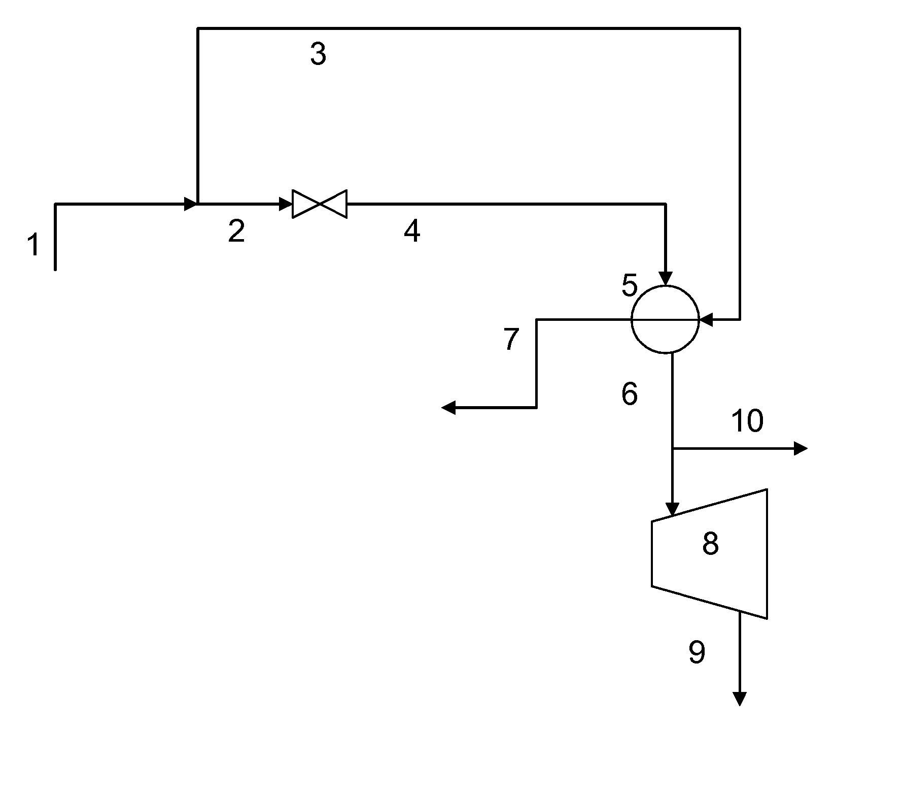
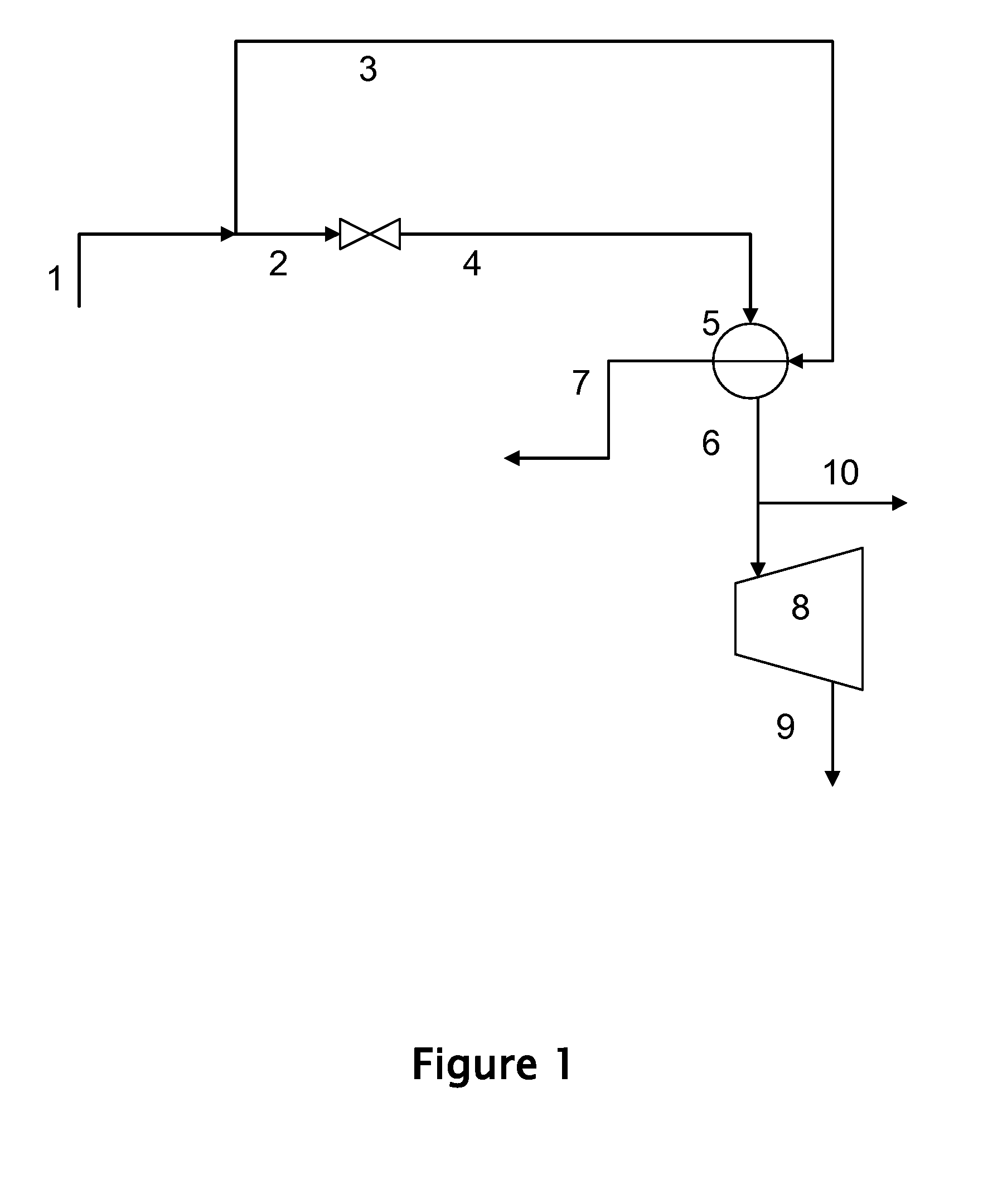
[0078] Examples 1-5 illustrate the effect on turbine outlet steam quality by changing the pressure to which the high pressure inlet steam is reduced as per FIG. 1 of the instant invention. 100,000 kg / hr of saturated high pressure steam at 131 bara and 331.45° C. is divided and a portion is reduced in pressure. The resulting lower pressure steam is subjected to heat exchange with the remaining portion of high pressure steam. The approach temperature in the heat exchanger is 5° C., i.e., the superheated lower pressure steam temperature is 326.45° C. in all cases. The superheated lower pressure steam is fed to a steam turbine with an outlet pressure of 0.12 bara and a mechanical efficiency of 86.5% to produce electricity. Table 1 shows results per the instant invention for various lower pressure values.
TABLE 1Effect of PressureLowerAmount ofTurbinePressureLower P SteamDegreesOutletSteam,(thousandsSuperheat,Electricity,SteambaraKg / hr)° C.MWQualityExample 165.579.245.118.879.5%Example ...
example 6
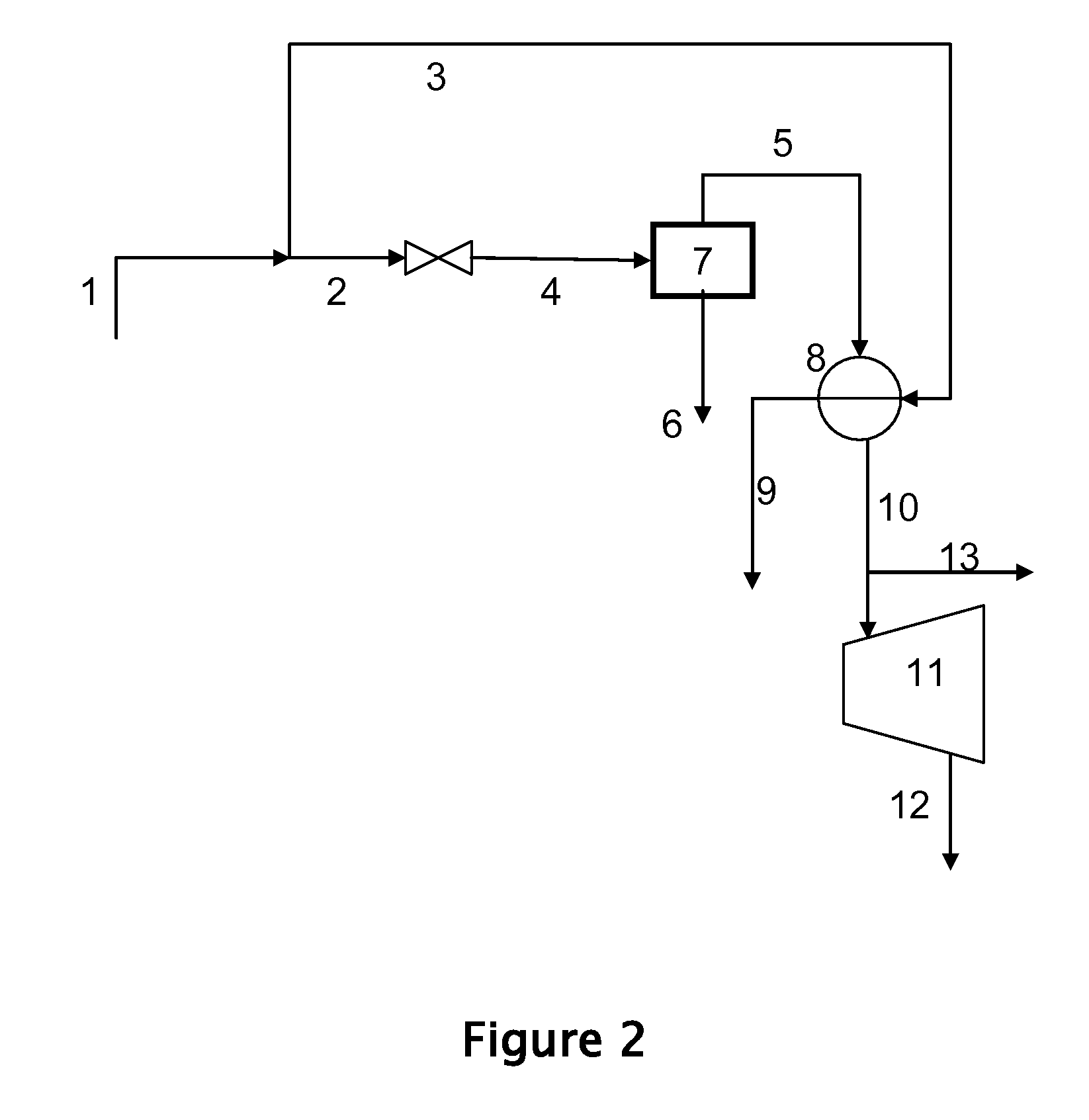
[0080] Example 6, following the nomenclature of FIG. 3, illustrates the overall efficiency of a steam cycle. Heat input into steam generating zone 17 via conduit 19 is 245.3 GJ / hr as in Comparative Example 2. 112,350 kg / hr of liquid water at 49.5° C., is boiled in heat transfer zone 17 to produce 112,350 kg / hr of saturated high pressure steam at 131 bara and 331.45° C. in conduit 1. 17,550 Kg / hr is diverted via conduit 3, the remainder of 94,800 kg / hr passes via conduit 2 and is flashed across a valve to produce saturated steam at 42.4 bara, 253.8° C., 91.8% quality. The resulting lower pressure steam is divided into 7800 kg / hr of saturated liquid in conduit 6 and 87,000 kg / hr of saturated vapor in conduit 5. Conduit 5 subjected to heat exchange with conduit 3 in exchanger 8. The approach temperature in the heat exchanger is 5° C., producing superheated lower pressure steam temperature at 326.45° C., 42.4 bara in conduit 10 and condensed high pressure steam at 331.45° C. in conduit ...
example 7
[0081] Example 7, following the nomenclature of FIG. 4, illustrates the overall efficiency of a steam cycle. Heat input into steam generating zone 17 via conduit 19 is 245.3 GJ / hr as in Comparative Example 2. 115,290 kg / hr of liquid water via conduit 16 is boiled in heat transfer zone 17 to produce 115,290 kg / hr of saturated high pressure steam at 131 bara and 331.45° C., exiting via conduit 1. 16,410 Kg / hr is diverted via conduit 3, the remainder of 98,880 kg / hr passes via conduit 2 and is expanded in steam turbine 20 with a mechanical efficiency of 86.5% to produce 4.4 MW of electricity, and saturated steam at 42.4 bara, 253.8° C., 82.3% quality. The resulting lower pressure steam is divided into 17510 kg / hr of saturated liquid in conduit 6 and 81,370 kg / hr of saturated vapor in conduit 5. Conduit 5 subjected to heat exchange with conduit 3 in exchanger 8. The approach temperature in the heat exchanger is 5° C., producing superheated lower pressure steam temperature at 326.45° C.,...
PUM
 Abstract
Description
Claims
Application Information