Animal Watering Valve Having Elastomeric Diaphragm

a technology of elastomeric diaphragm and watering valve, which is applied in the direction of valve details, valve arrangement, aviculture, etc., can solve the problems of exponential increase of the force required to deflect the valve stem and inconsistent flow

Active Publication Date: 2007-10-25
AVIDITY SCIENCE LLC
View PDF23 Cites 7 Cited by
  • Summary
  • Abstract
  • Description
  • Claims
  • Application Information

AI Technical Summary

Benefits of technology

[0009] In accordance with a first aspect of the invention, an animal watering valve is provided that includes a housing having an upstream inlet and a downstream outlet. The housing supports a valve seat, an elastomeric diaphragm, and a valve stem. The elastomeric diaphragm is disposed in the bore upstream of the valve seat and includes a perforated portion having apertures formed therethrough that having outlets, and a seat portion having a valve stem head abutment surface. A valve stem is located in the bore and extends from the diaphragm toward the outlet. The valve stem has a head that is clamped between the diaphragm and the valve seat and a tail that is laterally deflectable to move the valve stem head relative to the diaphragm from a seated position. Upon moving it to an unseated position, the valve stem head seals against the valve seat to prevent water flow though the valve to an unseated position in which the valve stem head pivots relative to the valve seat to permit water flows through the apertures of the diaphragm, between the valve stem head and the valve seat, and out of the valve, the valve stem head having an upstream surface that abuts the seat portion. At least portions of the flow aperture outlets in the diaphragm are located radially inwardly of and axially upstream of the upstream surface of the valve stem head.

Problems solved by technology

For instance, flow tends to be inconsistent with the direction and / or extent of valve stem deflection because the gap between the head of the valve stem and the valve seat is relatively small—even when the valve stem is deflected its maximum amount.
In addition, because the entire upstream surface of the valve stem head rests on the diaphragm, the forces required to deflect the valve stem increase exponentially with stem deflection—which can be a hindrance to small or weak animals.

Method used


Image

  • Animal Watering Valve Having Elastomeric Diaphragm
  • Animal Watering Valve Having Elastomeric Diaphragm
  • Animal Watering Valve Having Elastomeric Diaphragm

Examples


first embodiment

1. System Overview and Construction and Operation of First Embodiment

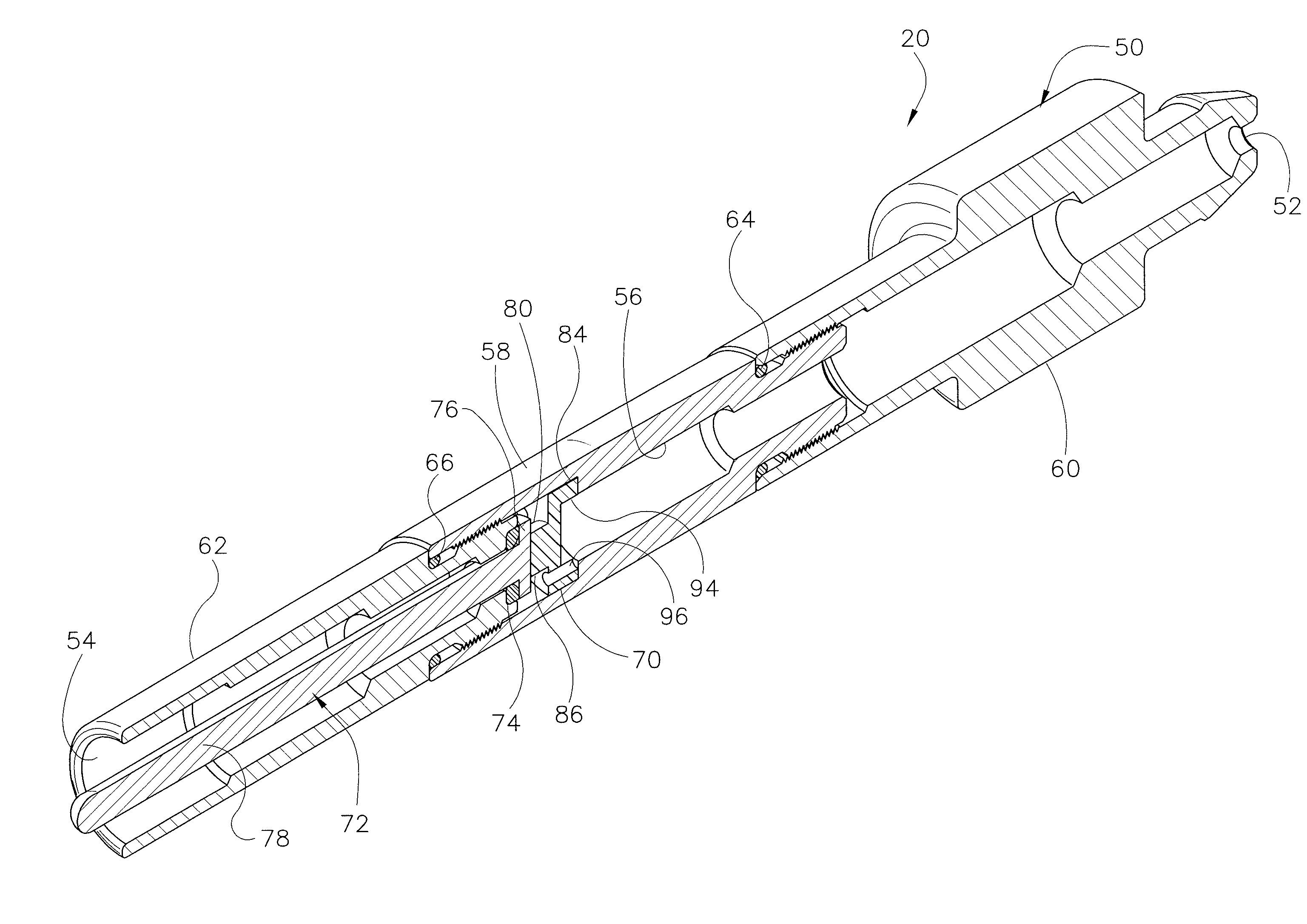
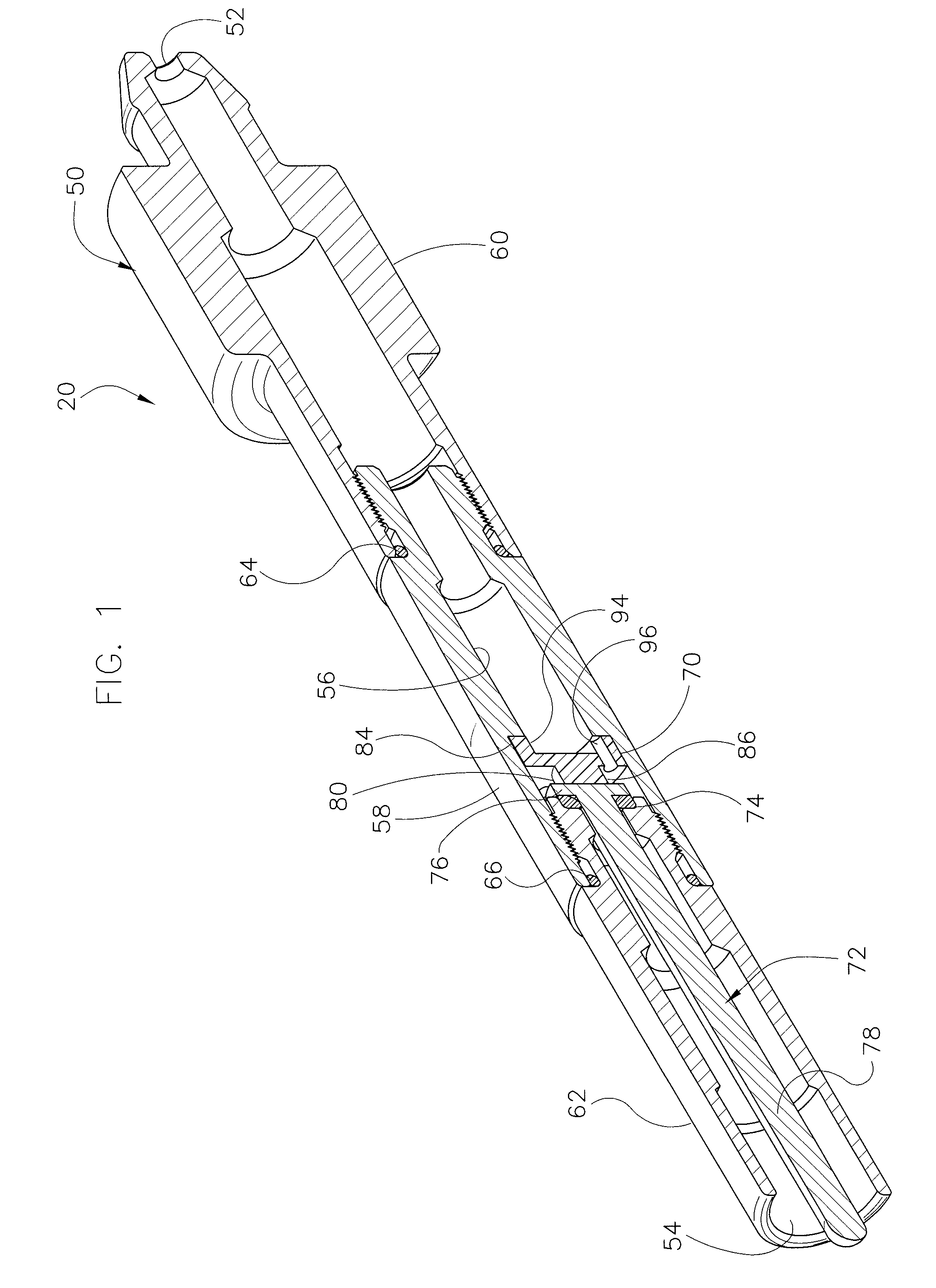
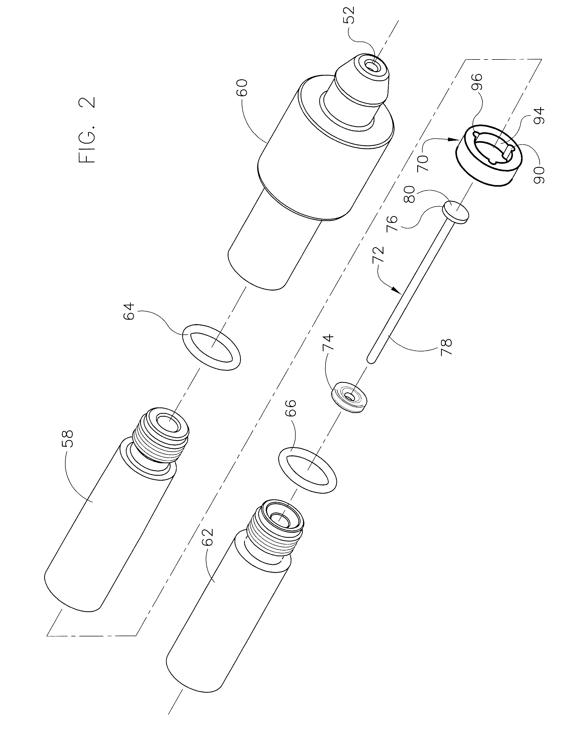
[0027] Referring now to FIGS. 1-5B, an animal watering valve 20 is illustrated which has many applications and which is particularly useful in an animal watering bag such as the one disclosed in co-pending and commonly assigned patent application Ser. No. 10 / 940,282, the subject matter of which is incorporated by reference. The animal watering valve 20 includes a housing 50 having formed therein an inlet 52, an outlet 54, and an elongated longitudinal bore 56 extending from the inlet 52 to the outlet 54. In order to facilitate assembly, the housing 50 is preferably formed from three axially aligned pieces including a body 58 a valve cap 60 threaded onto an upstream end of the body 58, and a valve guard 62 threaded onto a downstream end of the body 58. O-rings 64 and 66 seal the body 58 to the valve cap 60 and the valve guard 62, respectively. A diaphragm 70, valve stem 72, and valve seat 74 are clamped between the ...

second embodiment

2. Construction and Operation of Second Embodiment

[0036] Referring to FIGS. 6-10B, an animal watering valve 220 is illustrated which differs from the animal watering valve 20 of the first embodiment primarily in that it has a different diaphragm and has a shield 320 not found in the animal watering valve 20 of the first embodiment. It is also configured for direct mounting in a cage and connection to a hard water bottle or an animal watering system rather than for connection to an animal watering bag and, accordingly, has a slightly different housing. Elements of valve 220 corresponding to those of the valve 20 of the first embodiment are thus designated by the same reference numeral, incremented by 200.

[0037] Valve 220 includes a housing 250 which houses a diaphragm 270, a valve stem 272, and a seat 274. The housing 250 has formed therein an inlet 252, an outlet 254, and an elongated longitudinal bore 256 extending from the inlet 252 to the outlet 254. The housing 250 is formed fr...


PUM


Abstract

An animal watering valve has an elastomeric diaphragm disposed in a bore of a housing upstream of a valve seat and having apertures formed therethrough for the passage of water. A valve stem has a head clamped between the diaphragm and the valve seat and a tail that is laterally deflectable to move the valve stem head relative to the diaphragm from a seated position. Upon moving it to an unseated position, the valve stem head pivots relative to the valve seat to permit water to flow out of the valve. At least portions of the flow aperture outlets in the diaphragm are located radially inwardly of and axially upstream of the upstream surface of the valve stem head.

Description

BACKGROUND OF THE INVENTION [0001] 1. Field of the Invention [0002] The invention relates to animal watering valves and, more particularly, relates to animal actuated valves for use by mice, rats, and other relatively small laboratory animals or commercially raised animals. [0003] 2. Discussion of the Related Art [0004] Animal actuated watering valves are well known. One such valve is disclosed in U.S. Pat. No. 5,501,177, which issued to Edstrom on Mar. 26, 1996 (the Edstrom patent). The valve disclosed in the Edstrom patent employs a housing having an inlet and an outlet connected by an elongated longitudinal bore, a valve element located adjacent the inlet, and an elongated actuating lever or valve stem which extends through the bore, which projects out of the outlet, and which, when deflected by an animal, opens the valve element to permit the passage of fluid through the valve housing. A movable elastomeric boot is provided adjacent the outlet to inhibit the animal from stuffing...

Claims


Application Information

Patent Timeline
Patent Type & Authority Applications(United States)
IPC IPC(8): A01K7/00
CPCA01K39/0213A01K7/06
Inventor JOHNSON, PAUL S.
Owner AVIDITY SCIENCE LLC
Why Eureka
Try Eureka