
Wide angle solar concentrator

a solar concentrator and wide angle technology, applied in the field of optical, solar energy, lighting, etc., can solve the problems of limited methods, not truly non-imaging, and only increase the importance of solar energy, and achieve the effect of efficient collection and concentrating solar energy

Inactive Publication Date: 2007-10-25
APPLIED OPTICAL MATERIALS
View PDF22 Cites 32 Cited by
  • Summary
  • Abstract
  • Description
  • Claims
  • Application Information

AI Technical Summary

Benefits of technology

"The invention is an optical collecting and concentrating apparatus that can be used in various applications such as passive lighting, solar power, and optical communications. Unlike previous devices, this apparatus is non-imaging and non-planar, with a high acceptance angle. This means it can efficiently collect and concentrate solar energy even when the sun is at different angles. This is important because it eliminates the need for the apparatus to track the sun's movement."

Problems solved by technology

The efficient collection, concentration and distribution of solar energy remain some of the most significant, yet persistent problems of contemporary society.
As fossil fuels continue to dwindle in supply and contribute to undesirable environmental effects, the importance of solar energy will only increase.
These methods typically are limited by the range of acceptance angle of the optical system (i.e. they cannot collect over a wide range of incident solar angles), or are not truly non-imaging (i.e. they produce a poor image which still moves on the receiver as the sun moves relative to the collector).
Reflectors, lenses, Fresnel lenses, and similar optical instruments are all limited by this constraint.
While the devices of Afian et al and Rosenberg do make use of multiple diffraction events to steer a light ray, they are limited to planar formats and rely on partial transmission of the optical radiation through the hologram.

Method used


Image

  • Wide angle solar concentrator
  • Wide angle solar concentrator
  • Wide angle solar concentrator

Examples


Embodiment Construction

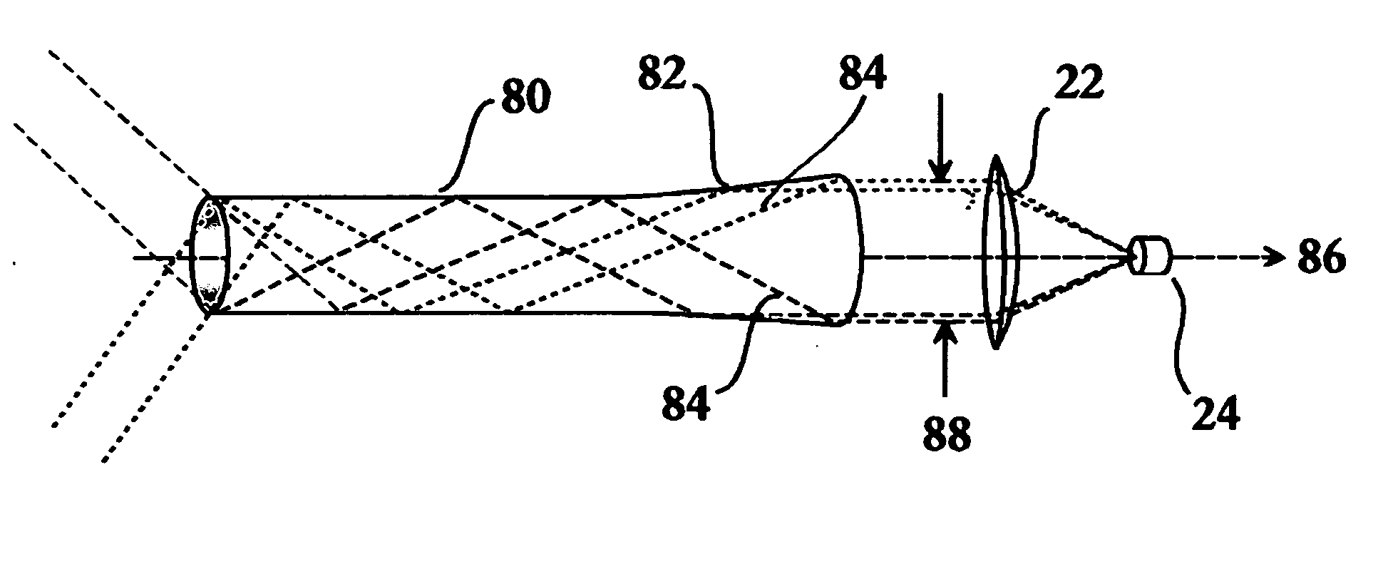
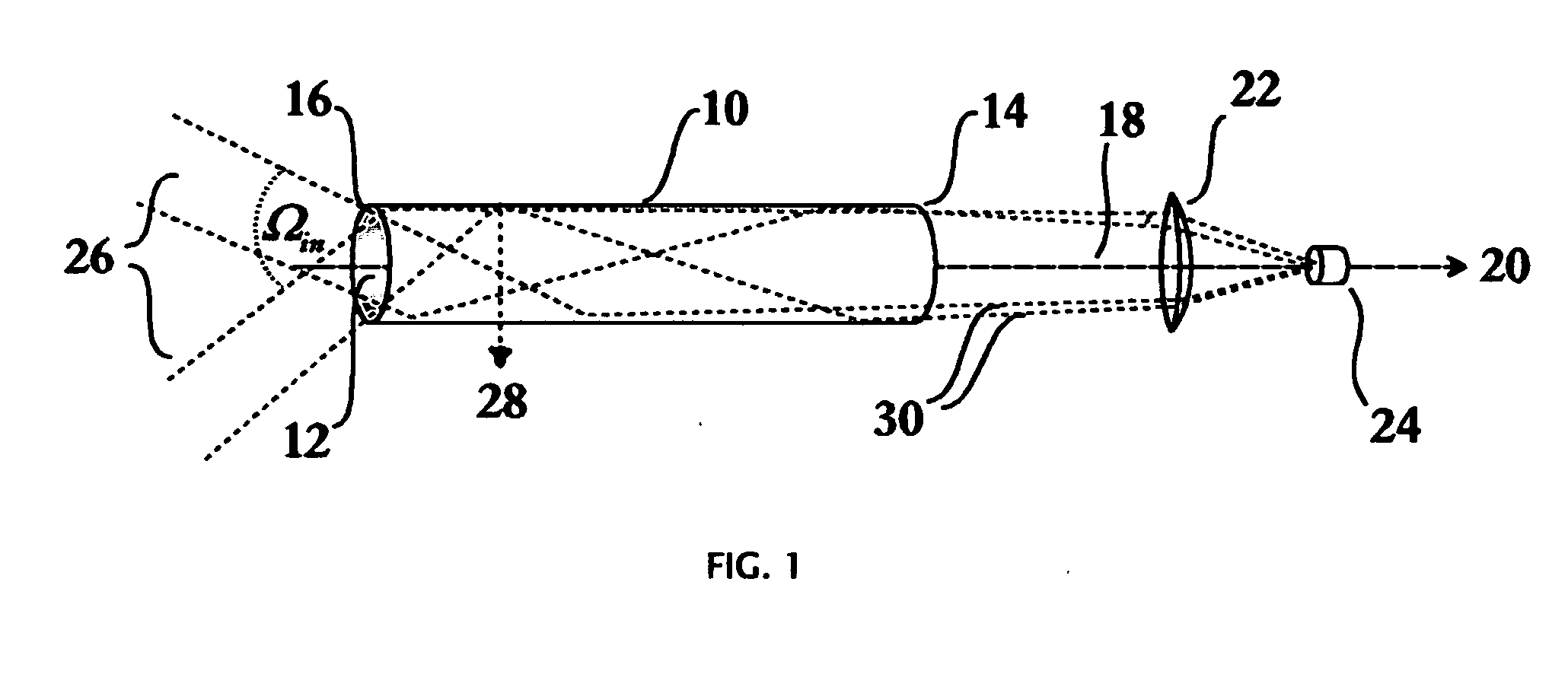
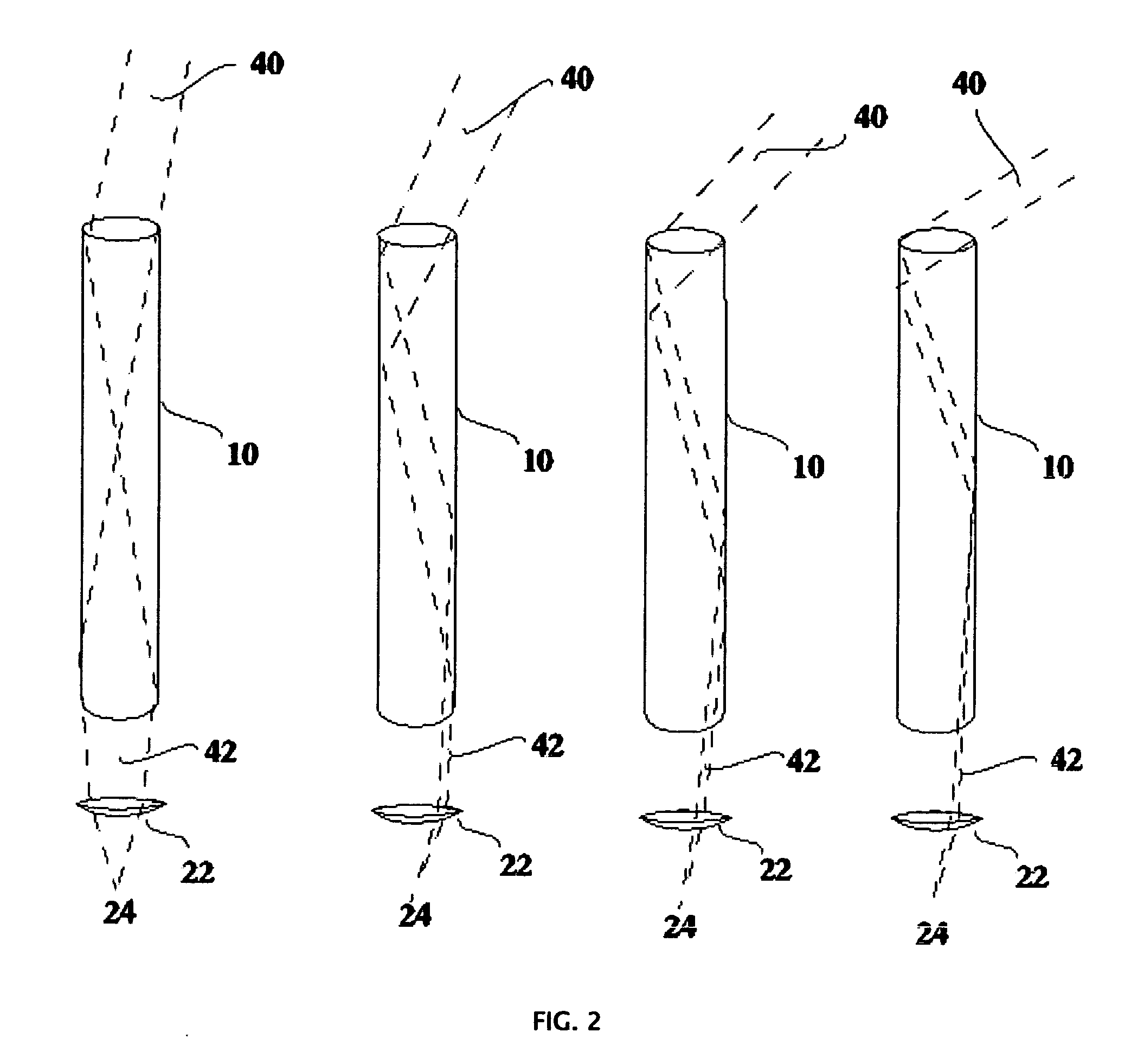
[0020]FIG. 1 shows a perspective view of a passive optical collection system constructed according to the present invention. More specifically collector tube 10 includes an optically diffractive medium 12 disposed on the inner surface thereof. This medium is designed to partially scatter, reflect, or diffract light of various wavelengths at an angle greater than the incident angle at which the light strikes the surface. The tube may be hollow or filled with a transparent or partially transparent medium. The net effect is that the output of the tube at a clear aperture 14 opposite the opening 16 where sunlight or other optical radiation is incident, is a beam 18 consisting of light rays which are substantially oriented in a direction parallel to the central axis 20 of tube 10. This beam thereafter impinges on a lens or similar optical element 22, which is designed so as to focus the collimated or nearly collimated beam 18 onto an optical receiver or collecting device 24. The lens ele...


PUM


Abstract

A non-imaging optical collecting and concentrating apparatus for use in i.e., optical communications, passive lighting, and solar power applications that is relatively immune from optical incidence angle(s) and therefore does not need to track the movement of the sun to efficiently collect and concentrate optical energy is described. The apparatus includes a tubular support structure having a source-facing entrance and an energy-outputting exit. An interior surface of the structure includes a scattering, reflecting and / or diffractive medium to direct incident energy toward an exit of the tubular structure, such that the rays exiting the tube are more collimated and substantially more parallel to the axis of the tube. The collimated beam is then focused or directed by a lens or similar optical element toward a point where the energy may be collected by a detector, optical fiber, or other collection means.

Description

FIELD OF THE INVENTION [0001] This invention relates generally to the fields of optics, solar energy, and lighting and in particular to an apparatus that efficiently collects and concentrates incident optical energy over a wide range of incident angles. BACKGROUND OF THE INVENTION [0002] The efficient collection, concentration and distribution of solar energy remain some of the most significant, yet persistent problems of contemporary society. Its importance cannot be overstated. As fossil fuels continue to dwindle in supply and contribute to undesirable environmental effects, the importance of solar energy will only increase. Efforts to realize the potential(s) of solar energy—and in particular efforts directed toward the efficient collection and concentration of solar energy—are therefore of great significance. [0003] The prior art has produced a variety of solar energy collectors and concentrators having a solar energy receiver upon which solar energy to be collected is directed....

Claims


Application Information

Patent Timeline
Patent Type & Authority Applications(United States)
IPC IPC(8): F24J2/08F24S23/30
CPCF24J2/06F24J2/08G02B19/0028G02B19/0042Y02E10/44F24S23/00F24S23/30
Inventor SCHAAFSMA, DAVID
Owner APPLIED OPTICAL MATERIALS
Learn More