
Method and apparatus for detecting defects using digital radiography

a digital radiography and defect detection technology, applied in the field of digital radiography, can solve the problems of ducts that are prone to flexing, eroded and cracking, and can be time-consuming and relatively expensive to apply the thermal barrier layer,

Inactive Publication Date: 2005-03-29
SIEMENS ENERGY INC
View PDF15 Cites 17 Cited by
  • Summary
  • Abstract
  • Description
  • Claims
  • Application Information

AI Technical Summary

Problems solved by technology

These severe environmental conditions can cause the ducts to develop various defect types and sizes, both in the panel surfaces and in the welds between the individual panels.
The gases are corrosive and experience wide temperature excursions, causing the ducts to flex, erode and crack.
Thus application of the thermal barrier layer can be a time-consuming and relatively expensive process.
If not identified and not timely repaired, such cracks or defects can grow; eventually causing a breach in the panel through which the hot exhaust gases can escape.
Heating the duct may cause internal defects to migrate to the surface, where they can be identified according the visual or dye penetrant tests.
There are known limitations to the film x-ray radiography technique.
If an x-ray reveals a denser region in a corner of the object, for example, it is not possible to determine whether that denser region is on the incident surface (i.e., with respect to the impinging x-ray) of the object, on the surface where the x-ray exits the object or in an interior region between these two surfaces.
However, it is known that higher energy x-rays reduce the contrast between regions of unequal density, thus reducing the ability to distinguish regions of different densities.
All of these complexities associated with x-ray radiography contribute to longer inspection times and therefore increased inspection costs.

Method used


Image

  • Method and apparatus for detecting defects using digital radiography
  • Method and apparatus for detecting defects using digital radiography

Examples


Embodiment Construction

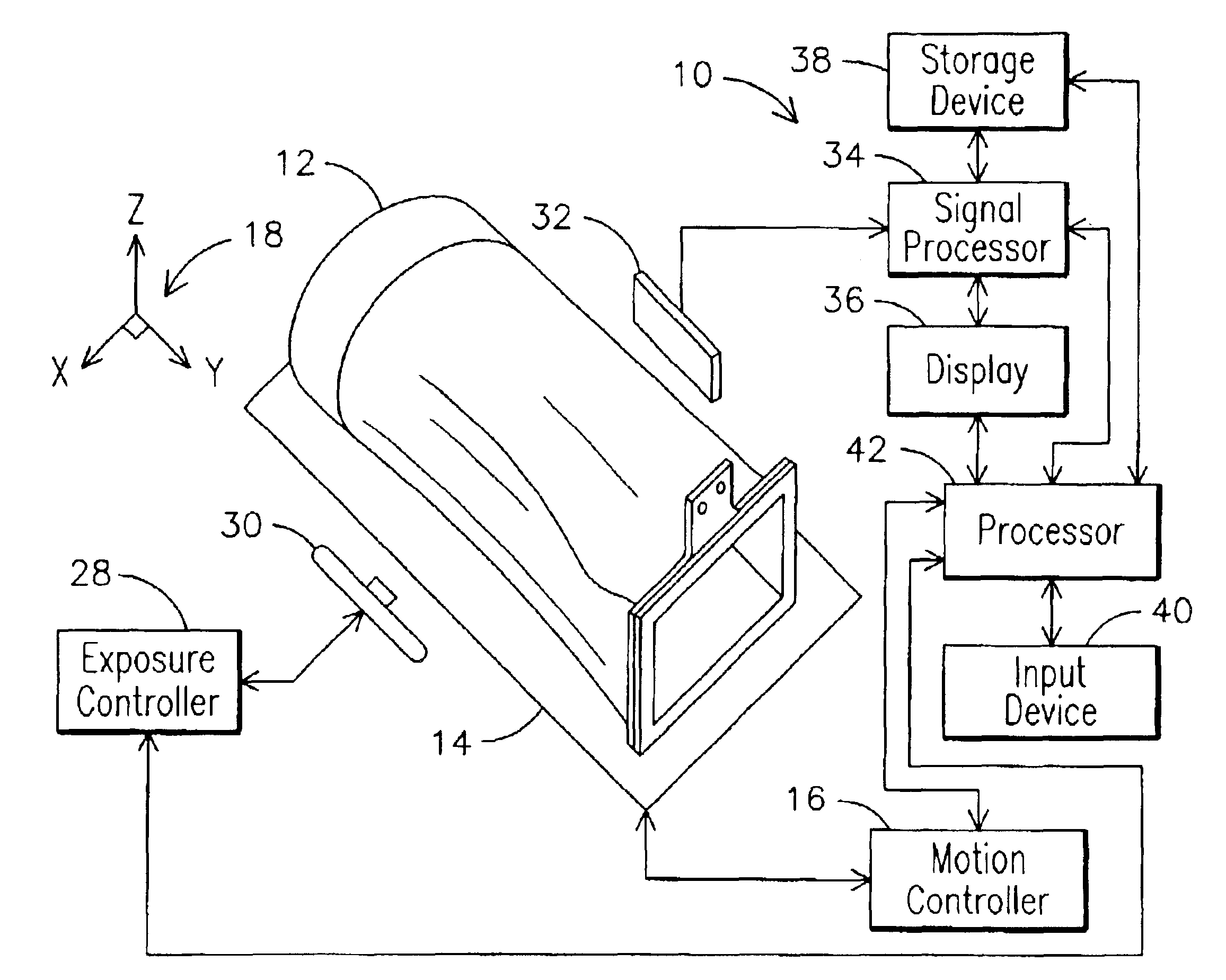
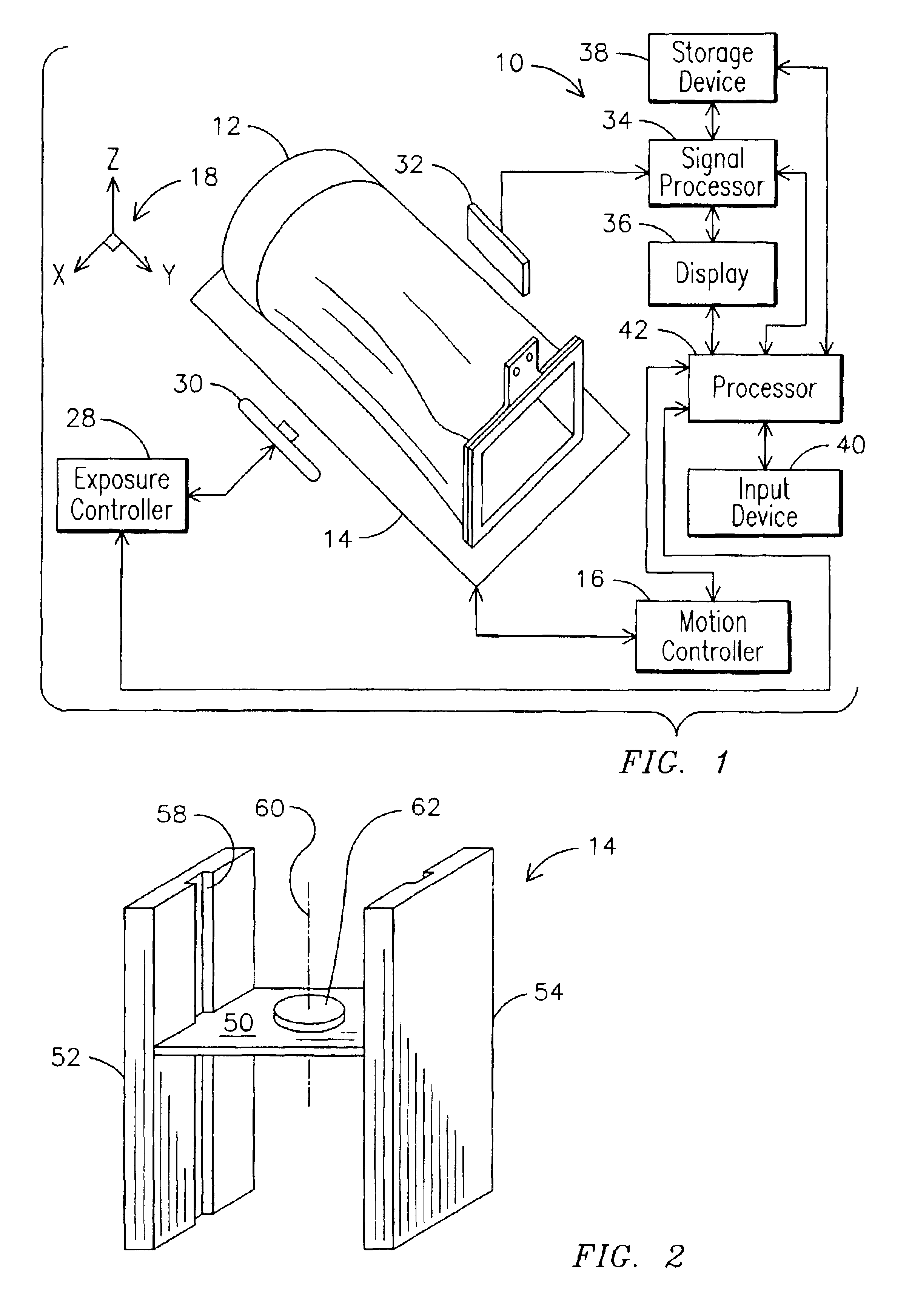
Before describing in detail the particular digital radiography based inspection method in accordance with the present invention, it should be observed that the present invention resides primarily in a novel and non-obvious combination of hardware elements and method steps. Accordingly, these elements and steps have been represented by conventional elements and steps in the drawings, showing only those specific details that are pertinent to the present invention so as not to obscure the disclosure with details that will be readily apparent to those skilled in the art and having the benefit of the description herein.

The use of digital radiography techniques for inspecting material pieces, such as the gas turbine transition exhaust ducts, offers several advantages over prior art techniques. The variability and subjectivity of the inspection results encountered with the visual and dye penetrant inspection tests described above are obviated by the creation of a stored permanent visual re...


PUM

PropertyMeasurementUnit
temperaturesaaaaaaaaaa
incident energyaaaaaaaaaa
energyaaaaaaaaaa

Abstract

A digital radiography apparatus (10) and process for providing images of an object, for example, an exhaust transition duct (12) comprising a core material and an overlying thermal barrier layer, to detect surface and interior defects within the duct (12). Incident energy is provided by an energy source (30), transmitted through the object (12), and sensed by a sensor (32). An image of the object (12) is formed by processing the signal from the sensor (32) in a signal processor (34) and displaying the image on a display (36) for determining defects in the object (12).

Description

FIELD OF THE INVENTIONThe present invention relates generally to digital radiography, and more particularly to the use of digital radiography to detect defects in metal parts.BACKGROUND OF THE INVENTIONRapid, efficient and accurate inspection of large industrial and machine parts is critical to determining defect existence and severity. Based on the inspection results, the user can determine whether the part can be effectively repaired or requires replacement. One such part of interest is the exhaust transition duct that carries hot exhaust gases from the combustion zone of a combustion turbine to external exhaust processing components. The gas combustion process imparts rotational energy to a shaft of an electrical generator, producing electricity for a power delivery system or for an industrial site. Certain gas turbines include as many as 16 exhaust transition ducts, each duct including as many as 20 individual and differently shaped panels welded together to form the duct. The p...

Claims


Application Information

Patent Timeline
Patent Type & Authority Patents(United States)
IPC IPC(8): G01N23/02G01N23/18G01N33/20
CPCG01N23/18G01N33/20G01N23/083G01N33/2045
Inventor JONES, JAMES WAYNE
Owner SIEMENS ENERGY INC
Learn More