
Piezoactuator

a technology of piezoelectric actuators and passivation materials, applied in the direction of piezoelectric/electrostrictive transducers, generators/motors, transducer types, etc., can solve the problems of electrical short circuit in particular, insufficient insulation properties of known passivation materials,

Inactive Publication Date: 2007-10-25
DELPHI TECH INC
View PDF0 Cites 19 Cited by
  • Summary
  • Abstract
  • Description
  • Claims
  • Application Information

AI Technical Summary

Benefits of technology

[0008] It was surprisingly able to be discovered within the framework of the present invention that glass, which is brittle and prone to breaking per se, is exceptional as passivation material for a piezoelectric component subject to dimensional changes during its operation, in particular when it is ensured that the coating of passivation material is permanently under compression during the operation of the piezoelectric component. In addition, it was able to be discovered within the framework of the present invention that glass is not only chemically resistant to fuel and moisture, but is sufficiently impermeable to these compounds, in particular also at the high temperatures prevailing in injection systems in diesel engines. Moreover, a coating of glass also has sufficient dielectric properties to achieve good electrical insulation of the surfaces coated therewith. Exceptional insulation of piezoelectric components can thus be achieved with the passivation material made from glass to be used in accordance with the invention by coating in particular those side surfaces of a piezoactuator at which the inner electrodes of different polarity are exposed.
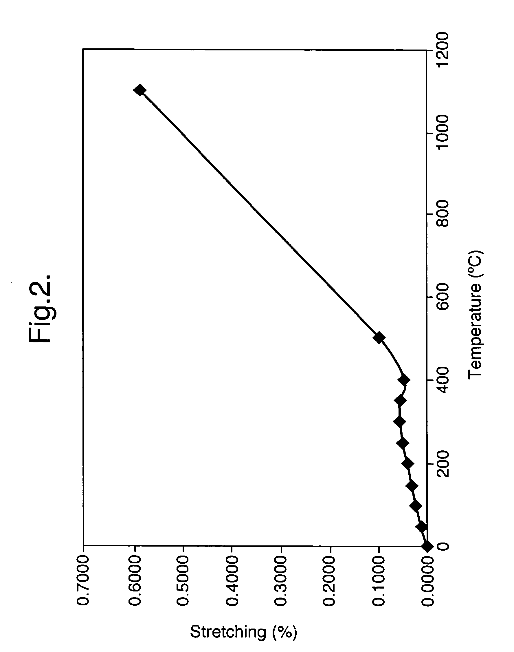
[0010] To avoid crack formation in the passivation material during the operation of the piezoelectric component, it is proposed in a further development of the idea of the invention to provide a passivation material which has a lower coefficient of thermal expansion than the piezoelectric component coated therewith. It is thereby ensured that the passivation material is in compression on the component.
[0020] It is proposed in a further development of the idea of the invention to coat the at least one side surface of the component with a passivation material which contains borosilicate glass and / or quartz glass or consists of borosilicate glass and / or of quartz glass. Due to the low coefficient of thermal expansion and the good resistance capability with respect to chemicals of the two aforesaid materials, crack formations in the passivation layer can be reliably avoided in the operation of the component.
[0033] The second poling in accordance with step g) of the method can take place directly after application of the two outer electrodes in accordance with step f) or also at a later point in time. The second poling is preferably carried out only after the complete assembly of the piezoelectric component since the component is best protected with respect to damaging influences at this point in time. It has in particular proved to be advantageous to carry out the second poling hydrostatically to ensure that the whole component remains in compression in the second poling.

Problems solved by technology

However, the insulation properties of the known passivation materials are not sufficient for all applications of piezoactuators.
In particular when the moisture content of the fuel amounts to more than 200 ppm, there is a risk with the known passivation materials that moisture will diffuse through the passivation layer and cause an electrical short circuit in particular at the side surfaces at which adjacent electrodes of different polarity are exposed.

Method used


Image

  • Piezoactuator
  • Piezoactuator
  • Piezoactuator

Examples


Embodiment Construction

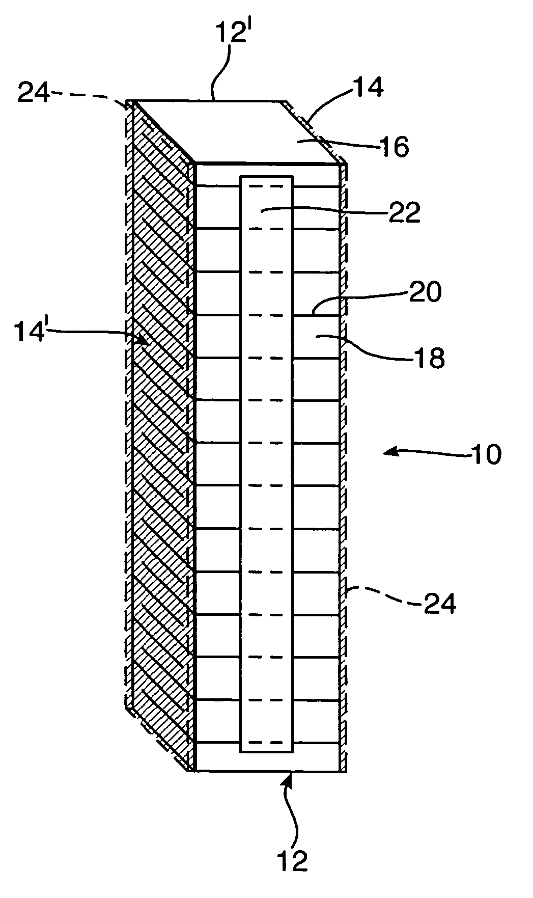
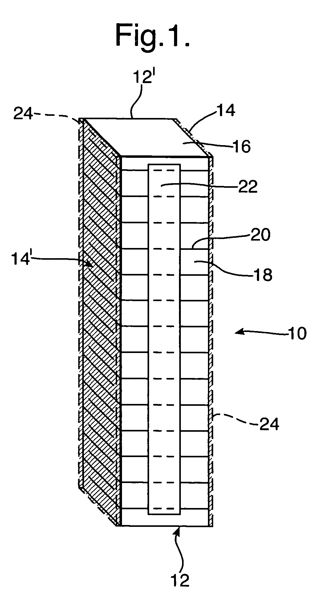
[0038] The piezoactuator 10 shown schematically in FIG. 1 is made in parallelepiped form and comprises a plurality of alternately arranged layers, which combine to define four side surfaces 12, 12′, 14, 14′, a base surface and a top surface 16. Piezoactuator 10 consists of alternately arranged layers of piezoelectric ceramic material 18 and inner electrodes 20, with the individual layers 18, 20 being arranged disposed over one another in the form of a stack and—with the exception of the topmost and bottommost layers—a respective piezoelectric ceramic layer 18 being surrounded by two inner electrodes 20 and each inner electrode 20 being surrounded by two respective piezoelectric ceramic layers 18.

[0039] An outer electrode 22, consisting of a metal layer, is in each case provided at the two oppositely disposed side surfaces 12, 12′ of the parallelepiped-shaped piezoactuator 10. The individual inner electrodes 20 are connected in each case alternately—viewed from the bottom to the top...


PUM

PropertyMeasurementUnit
Temperatureaaaaaaaaaa
Percent by massaaaaaaaaaa
Glass transition temperatureaaaaaaaaaa

Abstract

a piezoactuator having at least one outer surface comprises a multilayer structure of at least one piezoelectric ceramic layer and at least two electrodes, with the at least one outer surface of the piezoactuator being coated with a passivation material.

Description

TECHNICAL FIELD [0001] The present invention relates to a piezoelectric component, in particular to a piezoactuator, having at least one external surface and comprising a multilayer structure of at least one piezoelectric ceramic layer and at least two electrodes. The present invention furthermore relates to a method of manufacturing a piezoactuator. BACKGROUND OF THE INVENTION [0002] Known piezoactuators typically have a stack of alternating (inner) electrodes and piezoceramic layers, with the individual inner electrodes being surrounded at both sides by a piezoceramic layer in each case and the individual piezoceramic layers - with the exception of the ones arranged at the margin of the stack - being surrounded at both sides by an inner electrode in each case. In this connection, respectively adjacent inner electrodes separated from one another by a piezoceramic layer have different polarities; for example, the first, third and fifth inner electrodes of the stack have a positive p...

Claims


Application Information

Patent Timeline
IPC IPC(8): H02N2/04H01L41/23
CPCH01L41/0533Y10T29/42H01L41/23H01L41/083H10N30/883H10N30/50H10N30/02
Inventor SCIORTINO, GIACOMOGOAT, CHRISTOPHER A.
Owner DELPHI TECH INC
Learn More