Column based antenna array employing antenna field shaping for use in the automatic determination of network cable connections using RFID tags

Inactive Publication Date: 2007-10-25
LUCENT TECH INC
View PDF14 Cites 51 Cited by
  • Summary
  • Abstract
  • Description
  • Claims
  • Application Information

AI Technical Summary

Benefits of technology

[0010] We have recognized that with an appropriate antenna design, the row antennas used in Martin's disclosed antenna grid for use with a rectangular arrangement of device ports can be advantageously eliminated, thereby providing a method and apparatus for the automatic determination of cable connections employing a significantly reduced number of antennas (e.g., equal to the number of columns of device ports in a two-dimensional rectangular grid thereof, rather than equal to at least the sum of the number of columns plus the number of rows). In particular, in accordance with an illustrative embodiment of the present invention, each column antenna, positioned so as to be in close proximity to each of a set of device ports (e.g.; all device ports in a given column), advantageously comprises a series of resonators that correspond to the individual device ports (i.e., cable connector locations) in the set. Illustratively, these resonators may comprise in-line circuitry within the antennas, or other means for producing given impedance values at the cable connector locations. Then, in operation, the power supplied to a given antenna is varied (e.g., in a step-wise fashion), so that the antenna field may be advantageously shaped to include a given subset of the device ports in the set and to exclude the others, thereby allowing the system to read individual RFID tags (connected to particular device ports) selectively.

Problems solved by technology

The management of complicated networks such as telecommunications networks or sophisticated computer networks is tremendously expensive.
A substantial portion of this cost arises from incomplete, incorrect or ambiguous knowledge about a network.
For example, a telecommunications network operator may not have an accurate record of how network switches are configured, leading to failed attempts to fix problems or provision new services.
However, a more fundamental ambiguity arises at the physical level of network cable management.
However, it is very difficult to maintain an accurate record of exactly which cable is connected to which port of a given piece of equipment (e.g., a patch panel of a telecommunications switch), since the cables may so easily be connected, disconnected, and reconnected.
In a large telecommunications or computer network system, it is an extremely expensive proposition to keep track of every cable, where it is, where it runs, and which port on a given piece of equipment it is plugged into.
As a result, equipment inventory databases are notoriously inaccurate, and the negative results include, inter alia, loss of network capacity, increased service times and a much greater chance of disruptive service errors.
This, however, might be prohibitively expensive.
(As is familiar to those of ordinary skill in the art, whereas RFID tags are extremely inexpensive, RFID readers are typically not so inexpensive.)

Method used


Image

  • Column based antenna array employing antenna field shaping for use in the automatic determination of network cable connections using RFID tags
  • Column based antenna array employing antenna field shaping for use in the automatic determination of network cable connections using RFID tags
  • Column based antenna array employing antenna field shaping for use in the automatic determination of network cable connections using RFID tags

Examples


Embodiment Construction

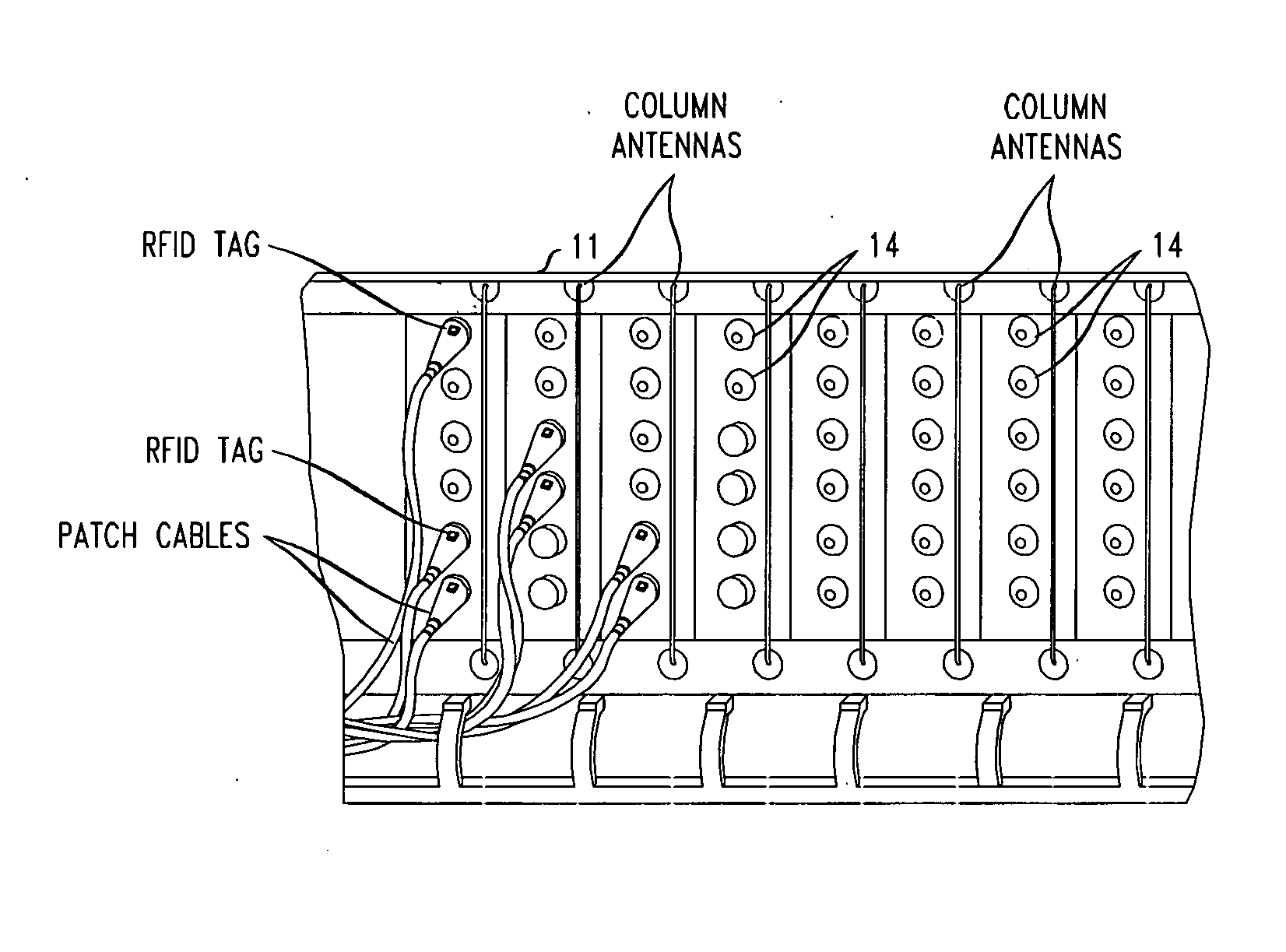
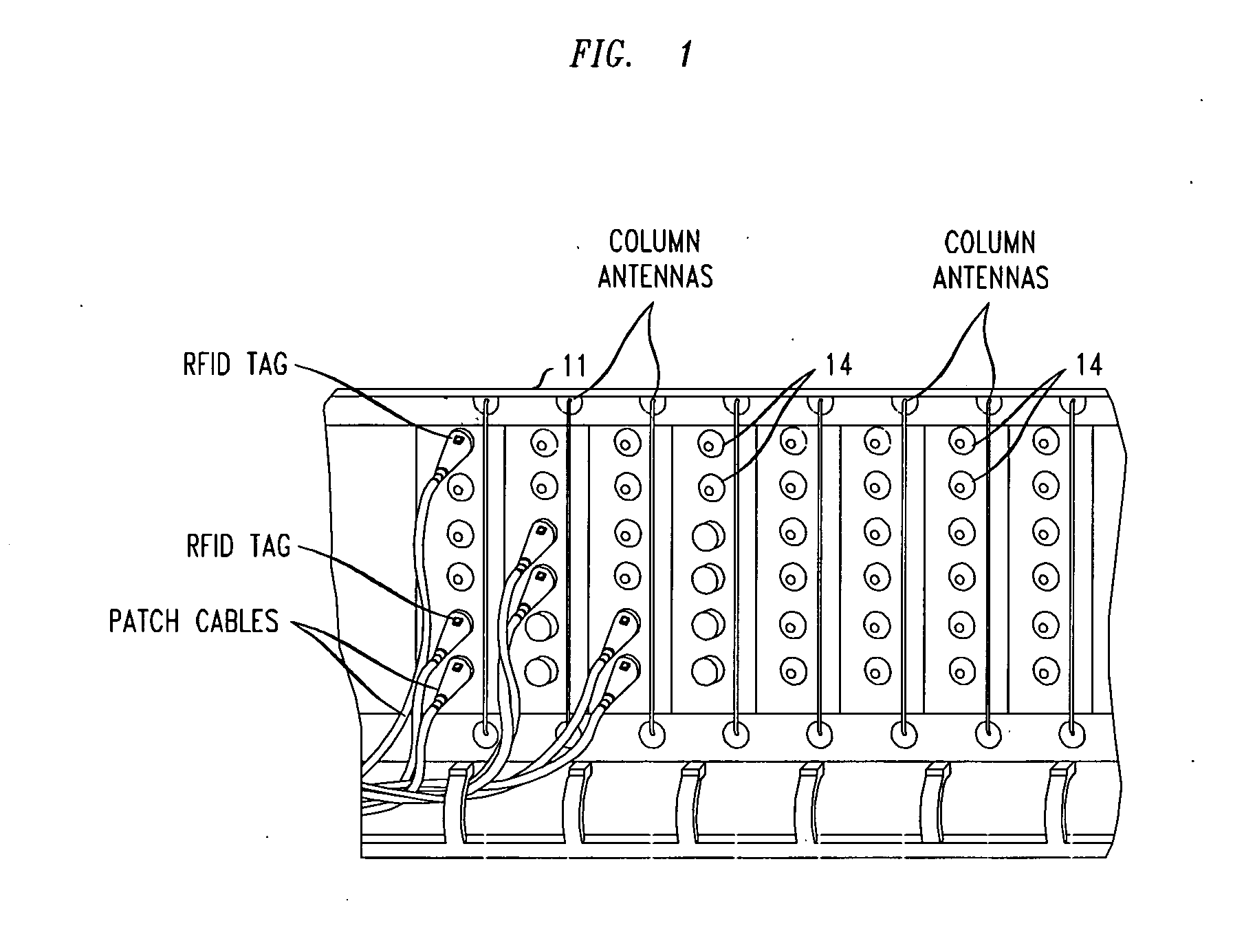
[0015]FIG. 1 shows an example of an apparatus comprising a patch panel having a plurality of RFID column antennas for the automatic determination of network cable connections in accordance with an illustrative embodiment of the present invention. The illustrative apparatus comprises patch panel 11 which comprises a plurality of device ports 14 which are arranged in a rectangular configuration. As such, each device port can be identified in terms of a physical column (e.g., horizontal position) number and a physical row (e.g., vertical position) number. As can be seen from the figure, the particular illustrative patch panel shown has 48 device ports, arranged in 8 (vertical) columns and 6 (horizontal) rows. In addition, note that certain ones of the device ports have corresponding patch cables connected thereto, each of which has a cable end (i.e., a plug) which advantageously has an RFID tag attached thereto. (Such RFID tags are conventional and are fully familiar to those of ordina...


PUM


Abstract

A method and apparatus for the automatic determination of cable connections on a patch panel employs a reduced number of RFID antennas. A plurality of RFID antennas, each positioned so as to be in close proximity to each of a set of device ports of a patch panel, each comprises a series of resonators that correspond to the individual device ports (i.e., cable connector locations) in the set. The resonators may comprise in-line circuitry within the antennas, or other means for producing given impedance values at the cable connector locations. In operation, the power supplied to a given antenna is varied (e.g., in a step-wise fashion), so that the antenna field may be advantageously shaped to include a given subset of the device ports in the set and to exclude the others, thereby allowing the system to read individual RFID tags (connected to particular device ports) selectively.

Description

FIELD OF THE INVENTION [0001] The present invention relates generally to the field of Radio Frequency Identification (RFID) systems and more particularly to the use of RFID techniques for the automatic determination of network cable connections. BACKGROUND OF THE INVENTION [0002] The management of complicated networks such as telecommunications networks or sophisticated computer networks is tremendously expensive. A substantial portion of this cost arises from incomplete, incorrect or ambiguous knowledge about a network. For example, a telecommunications network operator may not have an accurate record of how network switches are configured, leading to failed attempts to fix problems or provision new services. This lack of knowledge can in some instances be remedied by polling the networking equipment to determine its actual settings. [0003] However, a more fundamental ambiguity arises at the physical level of network cable management. Network cables may be added, removed or moved b...

Claims


Application Information

Patent Timeline
IPC IPC(8): H04Q5/22
CPCG06K7/10316H04Q1/149H01Q1/2216
Inventor MARTIN, CLIFFORD E.NG, WEE TECKTRAN, CUONG
Owner LUCENT TECH INC
Why Eureka
Try Eureka