Intramedullary Nail

a technology for intramedullary nail and nail, applied in the field of intramedullary nail, can solve the problems of excessive damage to the spongy part, difficult to line up said screws with the holes in the nail, and the difficulty of implanting said cross screws is considerably more pronounced

Inactive Publication Date: 2007-10-25
ARA PINILLA JAVIER +2
View PDF26 Cites 18 Cited by
  • Summary
  • Abstract
  • Description
  • Claims
  • Application Information

AI Technical Summary

Benefits of technology

[0002] The object of the invention is to achieve an elastic nail that is easier to implant in the bone, thus causing less damage thereto and improving the fixation, which also helps the bone to knit together.

Problems solved by technology

This solution has certain problems, particularly with regard to the following aspects: As the bones to be immobilised are not straight, the nail tends to become deformed as it is hammered in, with the risk of passing through the bone, causing excessive damage to the spongy part thereof, which separates the intramedullary canal from the hard outer layer.
Its fixation necessitates the use four cross screws and it is quite difficult to line up said screws with the holes in the nail.
The difficulty of implanting said cross screws becomes considerably more pronounced in the case of the lower or distal holes, and the use of x-rays is not acceptable to surgeons, as they are frequently exposed to high radiations, particularly on their hands.
Although guiding systems exist in order to help to centre the holes, as do other systems with a “probe hole” wherein a guide is used to indicate the position of the holes in the nail, these solutions do not solve the above-described problems.
Although this solution substantially simplifies the operating system and minimises the use of x-rays, it does present certain problems with regard to the following It is not very secure.
The thin filaments or rods can damage the bone.
The fixation is arbitrary, as the deformation and manner in which the filaments are driven into the bone is not controllable.

Method used


Image

  • Intramedullary Nail
  • Intramedullary Nail
  • Intramedullary Nail

Examples


Embodiment Construction

[0016] The intramedullary nail proposed by the invention successfully solves the above-described problems in each of the aspects that have been mentioned.

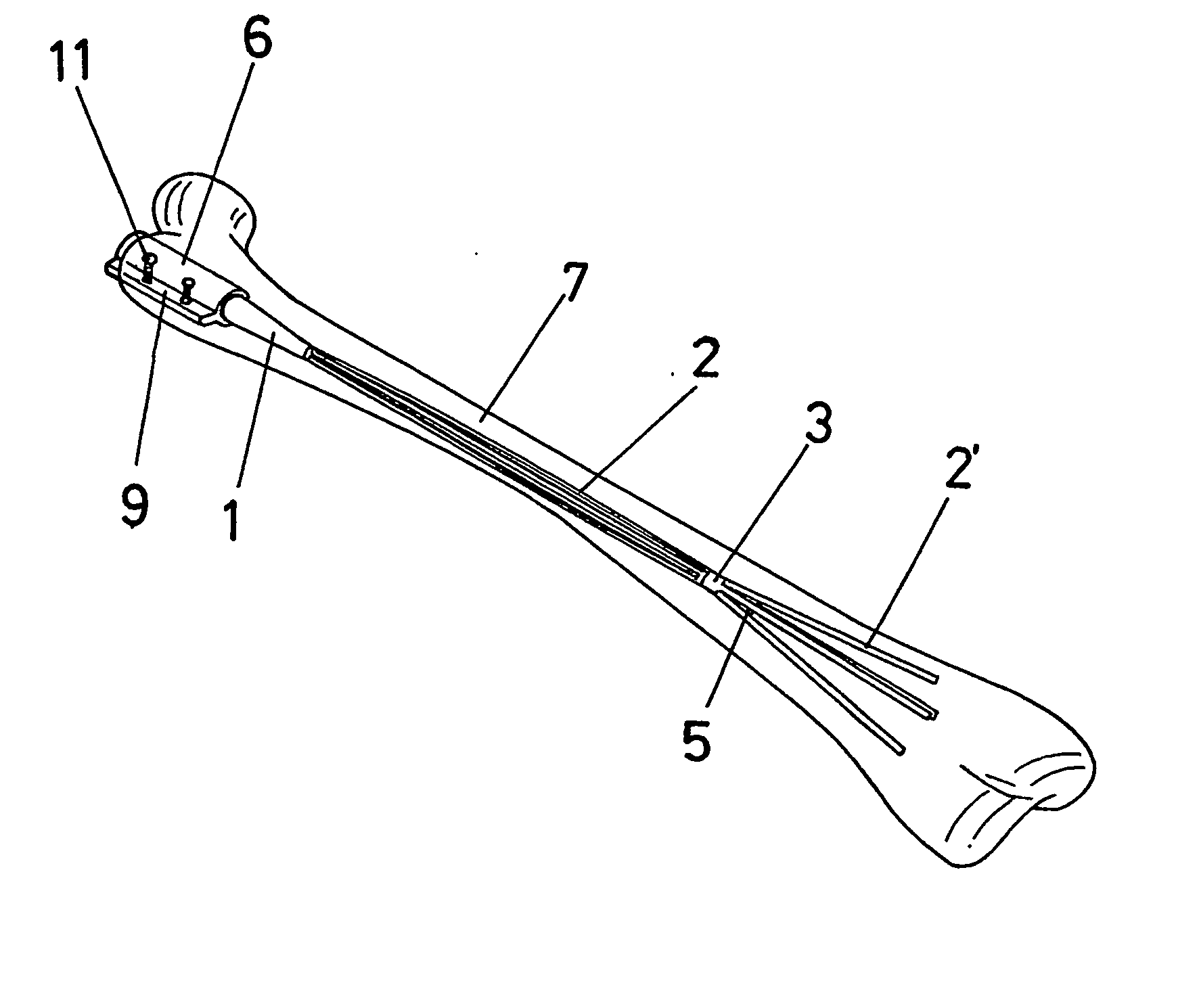
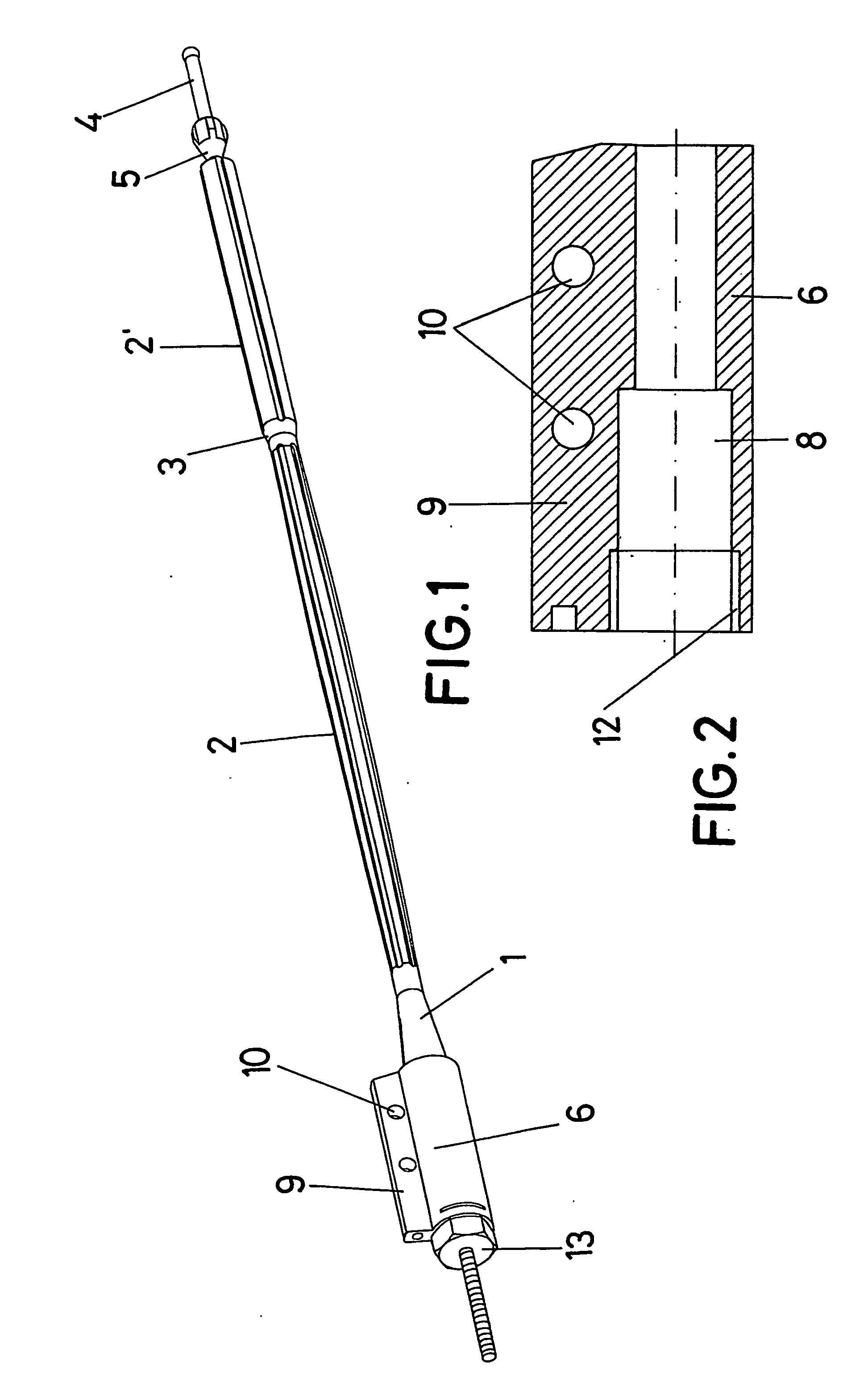
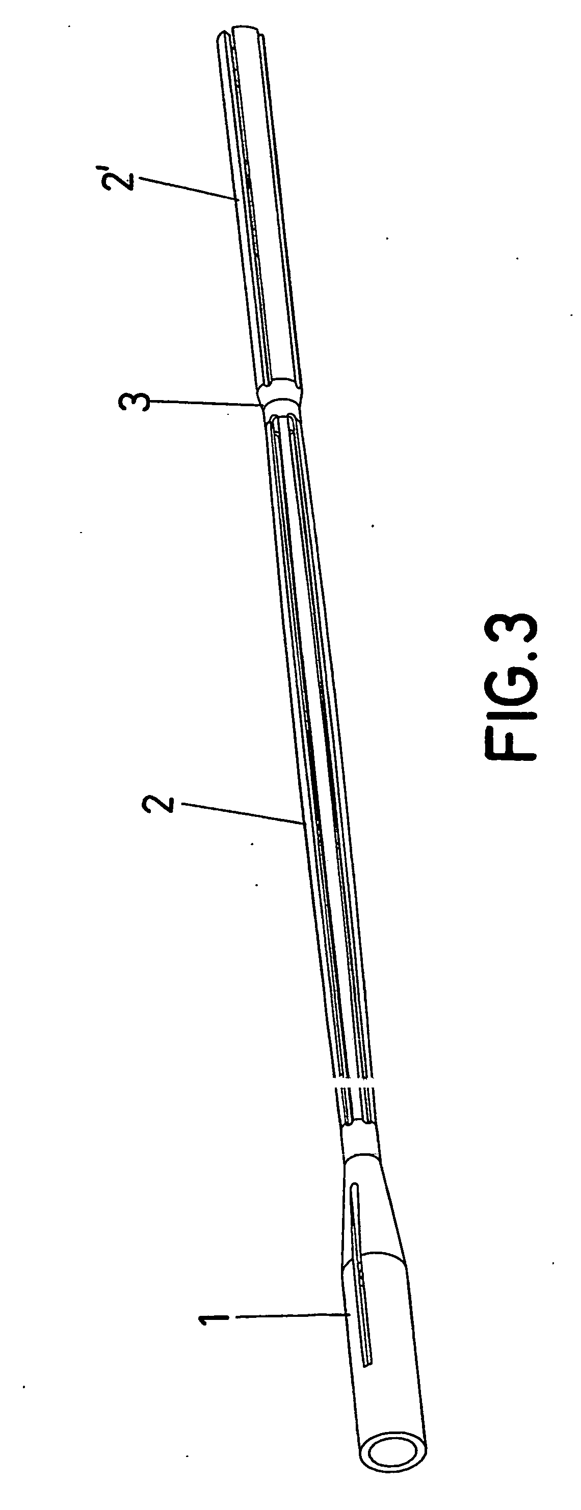
[0017] More specifically, to do this said nail consists of a functional combination of a nail and a probe that can move axially inside the nail, the purpose this probe being to cause a radial deformation of the nail, so that this need only be fixed by screws at the proximal end of the bone, whilst it is fixed at the distal end by said expansion effect.

[0018] This is achieved thanks to the fact that the nail itself has a plurality of filaments extending from a head at its proximal end, which are disposed according to an imaginary cylindrical surface and which converge at a node that is considerably distanced from the head, beyond which said filaments extend in a wide section, the probe including a marked protrusion close to its distal end, so that, once the nail-probe assembly has been implanted inside the bone, as the probe moves...


PUM


Abstract

The invention relates to an intramedullary nail. More specifically, the invention relates to a structure which combines a tubular nail (1-2-3-2′), a probe (4) which can move axially inside the tubular nail and a bone-fixing support (6), such as to form a head (1) on said nail, from which a plurality of thin rods (2) extend integrally. The rods are distributed over a considerably-long imaginary cylindrical surface having a reduced diameter and meet at a node A(3), beyond which they extend into segments (2′)j having an independent free end. According to the invention, a projecting part (5) of the probe (4) acts on the aforementioned segments (2′) when the probe is moved towards the head (1), in order to produce the radial deformation of the rods (2′) such as to enable same to penetrate the spongy bone tissue. When the protrusion (5) reaches the node (3) of the nail, said node (3) moves towards the head (1), thereby causing the radial expansion of the above-mentioned segment (2) of the rods. In this way, the rods adapt to the inner wall of the bone, exerting an elastic tension for improved fixing, said fixing necessitating only the screws that are used to stabilise the support (6) to which the head (1) of the nail is subsequently fixed internally.

Description

OBJECT OF THE INVENTION [0001] The present invention relates to an intramedullary nail, of the type used to secure and immobilise fractures in long bones such as the femur. [0002] The object of the invention is to achieve an elastic nail that is easier to implant in the bone, thus causing less damage thereto and improving the fixation, which also helps the bone to knit together. BACKGROUND OF THE INVENTION [0003] Nails are usually used to immobilise a long fractured bone, being hammered into one of the ends of the bone and having at each end a pair of holes for receiving respective cross screws that immobilise the nail by securing it to the two parts of the bone and consequently joining said fractured parts to one other. [0004] This solution has certain problems, particularly with regard to the following aspects: [0005] As the bones to be immobilised are not straight, the nail tends to become deformed as it is hammered in, with the risk of passing through the bone, causing excessive...

Claims


Application Information

Patent Timeline
Patent Type & Authority Applications(United States)
IPC IPC(8): A61B17/72
CPCA61B17/7266A61B17/7241
Inventor ARA PINILLA, JAVIERDE LA BARREDA LOPEZ, GUILLERMOMONOPOLI FORLEO, DONATO
Owner ARA PINILLA JAVIER
Why Eureka
Try Eureka