Picture-in-picture mosaic

Inactive Publication Date: 2007-10-25
SOUND VIEW INNOVATIONS
View PDF3 Cites 72 Cited by
  • Summary
  • Abstract
  • Description
  • Claims
  • Application Information

AI Technical Summary

Benefits of technology

[0018] Advantageously, the method of the invention provides a cost-effective and resource-efficient technique to provide advanced pi

Problems solved by technology

Some users find that using the DVD/VCR as the second tuner can be difficult to hook-up and confusing to use.
However, due to the high computational overhead associated with the derivation of reduced-size images, dedicated decoding hardware is also employed for these features, often requiring completely separate decoding hardware for the reduced-size image production.
As a result, the current system

Method used


Image

  • Picture-in-picture mosaic
  • Picture-in-picture mosaic
  • Picture-in-picture mosaic

Examples


Embodiment Construction

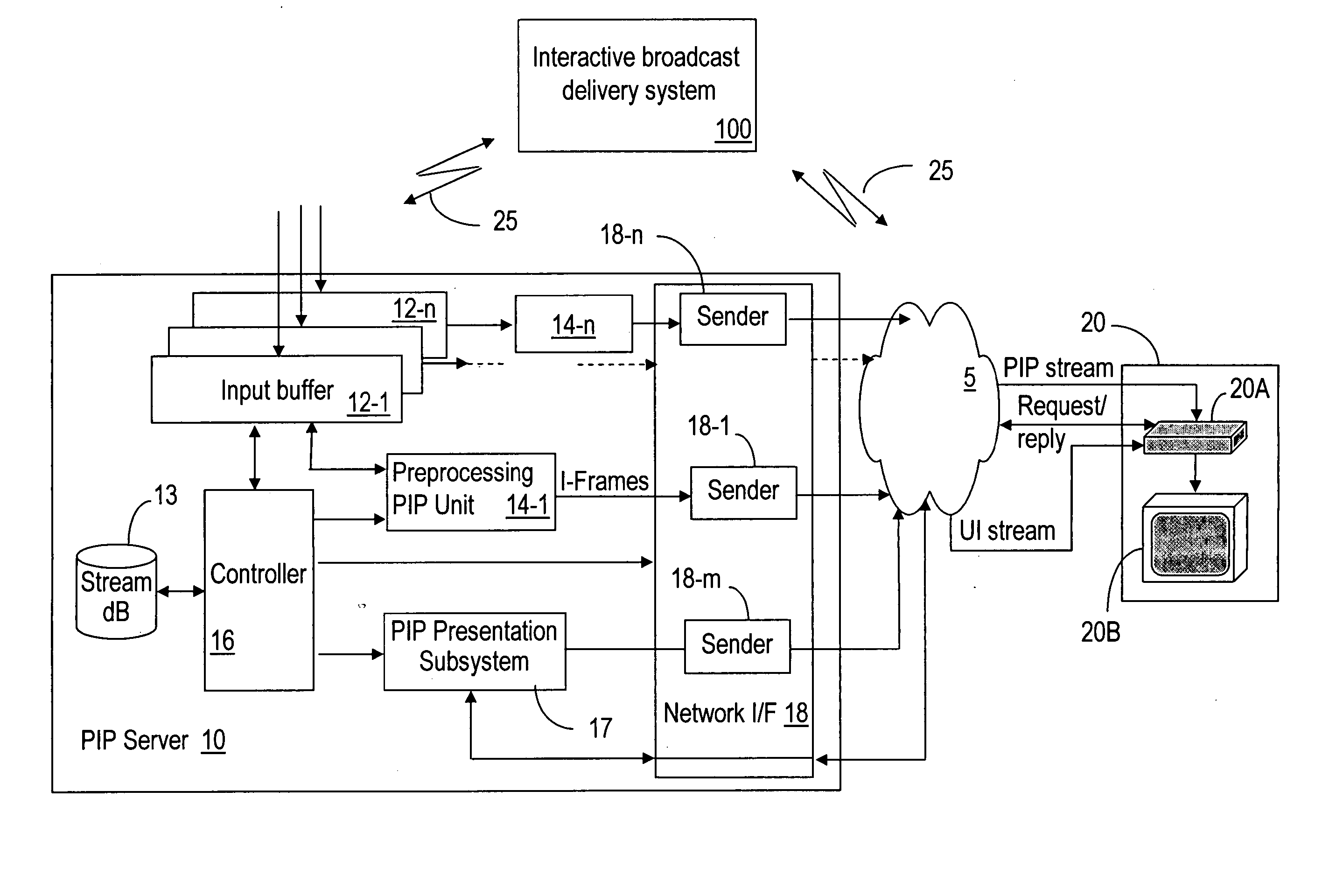
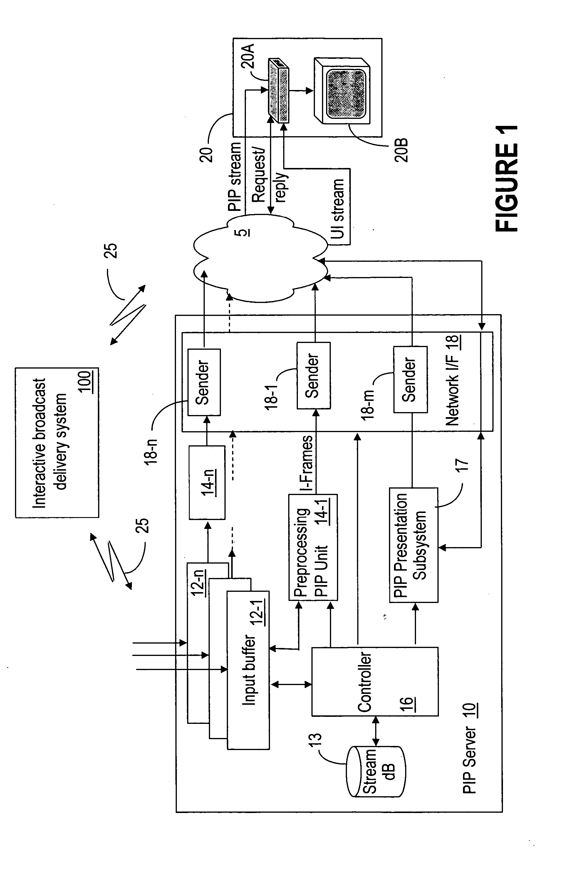
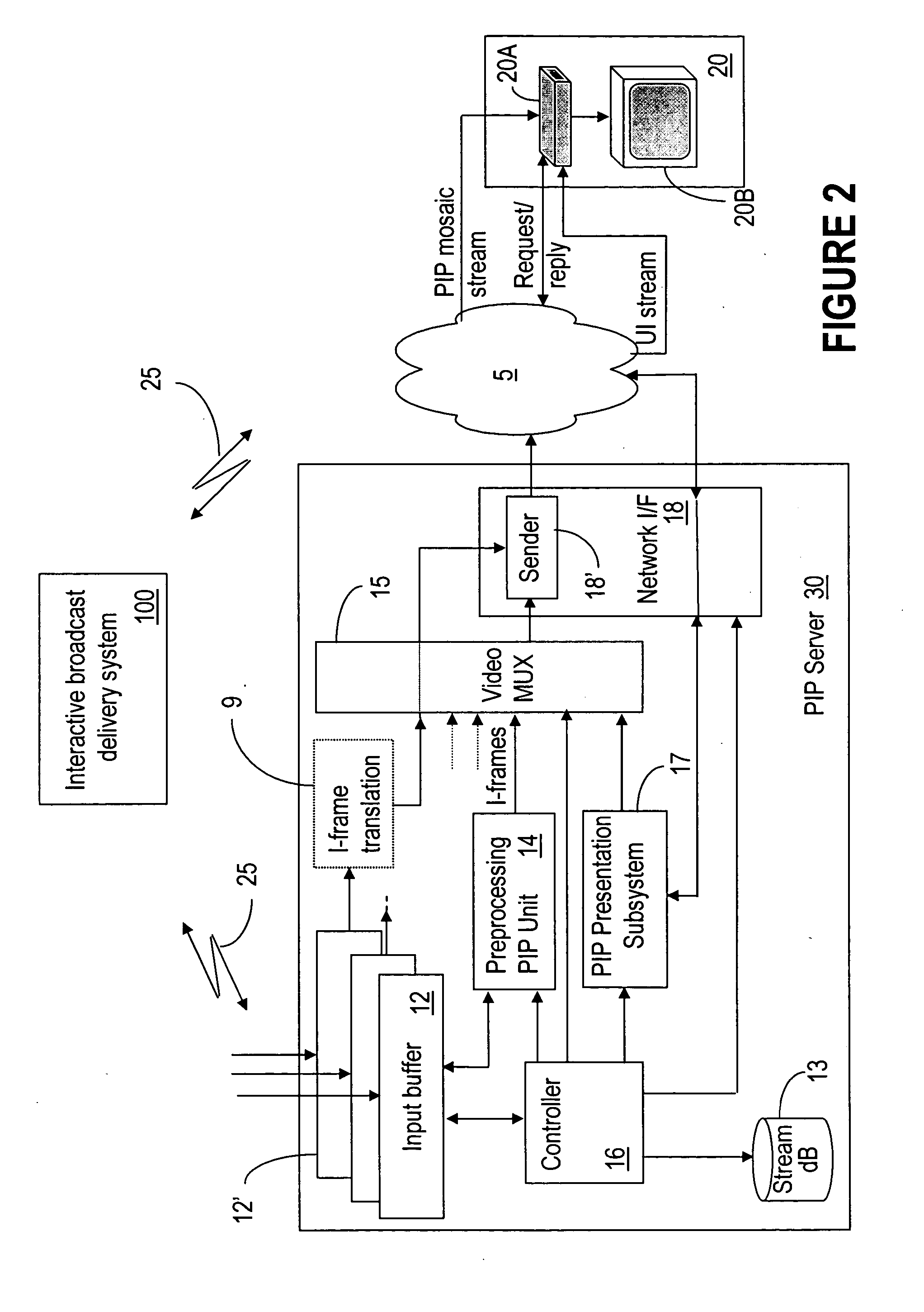
[0024] The invention is described next in connection with the MPEG2 trans[AJP1]port streams which are popular today; however, the invention is not restricted to MPEG technology. A brief description of a MPEG video stream is provided next for enabling an explanation of how the invention works by way of example. The MPEG-2 video compression standard achieves high data compression ratios by producing information for a full frame video image only every so often, and getting rid of the redundant information which would normally be in every single frame of video. Thus, an MPEG encoder actively selects frames to be used as I-Frames; the qualification as an I-Frame (Intra-Frame) is that there needs to be a “significant change” from the frame before it (like an explosion, or a new character in a scene, etc). If changes are minimal, an I-Frame is transmitted every N frames in the video stream where N is typically 12 or 15.

[0025] The intervening frames between the I-Frames are obtained by usi...


PUM


Abstract

The PIP system enables display of a mosaic of favorite channels in a Picture-in-Picture (PIP) format to a subscriber terminal. Picture-in-Picture support is efficiently provided by sending only I-Frames of the secondary video channel to the end-user. That is, any unnecessary packets (null, B-P frames, audio, etc.) in the secondary video channel are stripped away. This method uses very little bandwidth and is STB agnostic.

Description

FIELD OF THE INVENTION [0001] The invention is directed to communication networks and in particular to methods and apparatus for implementing a picture-in-picture (PIP) mosaic. BACKGROUND OF THE INVENTION [0002] The use of digital signals for television broadcasts and the transmission of other types of video and audio signals allow a significant improvement in picture quality and a more efficient use of bandwidth over that currently possible using analog television signals. The Advanced Television Systems Committee (ATSC) is a standards organization that was created to promote the establishment of technical standards for all aspects of advanced television systems. The ATSC adopted 8-VSB (vestigial sideband) standard radio frequency modulation format for the broadcast of digital TV signals, because of its large bandwidth, which is needed to transmit HDTV programming. With this carrier modulation type, the modulating data appears in the form of signal components at frequencies slightl...

Claims


Application Information

Patent Timeline
IPC IPC(8): G06F3/048H04N7/16H04N5/445G06F13/00G06F3/00H04N7/173
CPCH04N5/45H04N7/163H04N21/23418H04N21/23424H04N21/8549H04N21/4316H04N21/44016H04N21/8153H04N21/234336
Inventor PARKER, ALISTAIR JOHNFURLONG, JEFFDION, GINO LOUISHIGGINS, SEAN GORDONROBINSON, DAVID CECIL
Owner SOUND VIEW INNOVATIONS
Why Eureka
Try Eureka