

Door closer
- Summary
- Abstract
- Description
- Claims
- Application Information
AI Technical Summary
Benefits of technology
Problems solved by technology
Method used
Image

Examples
first embodiment
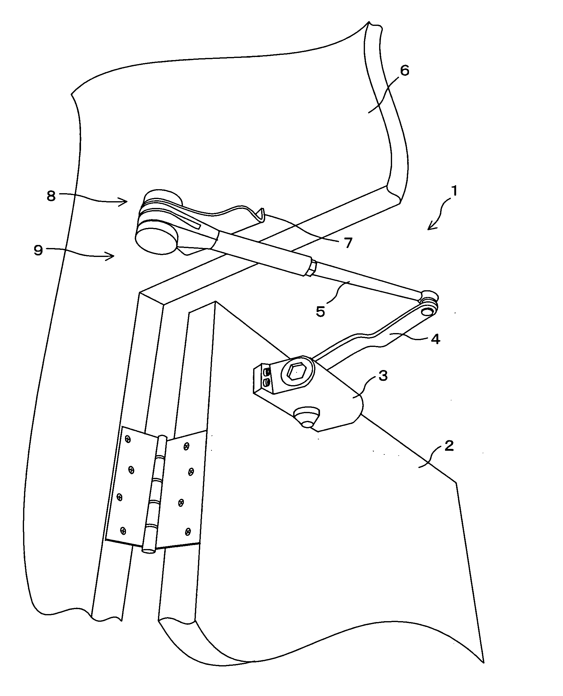
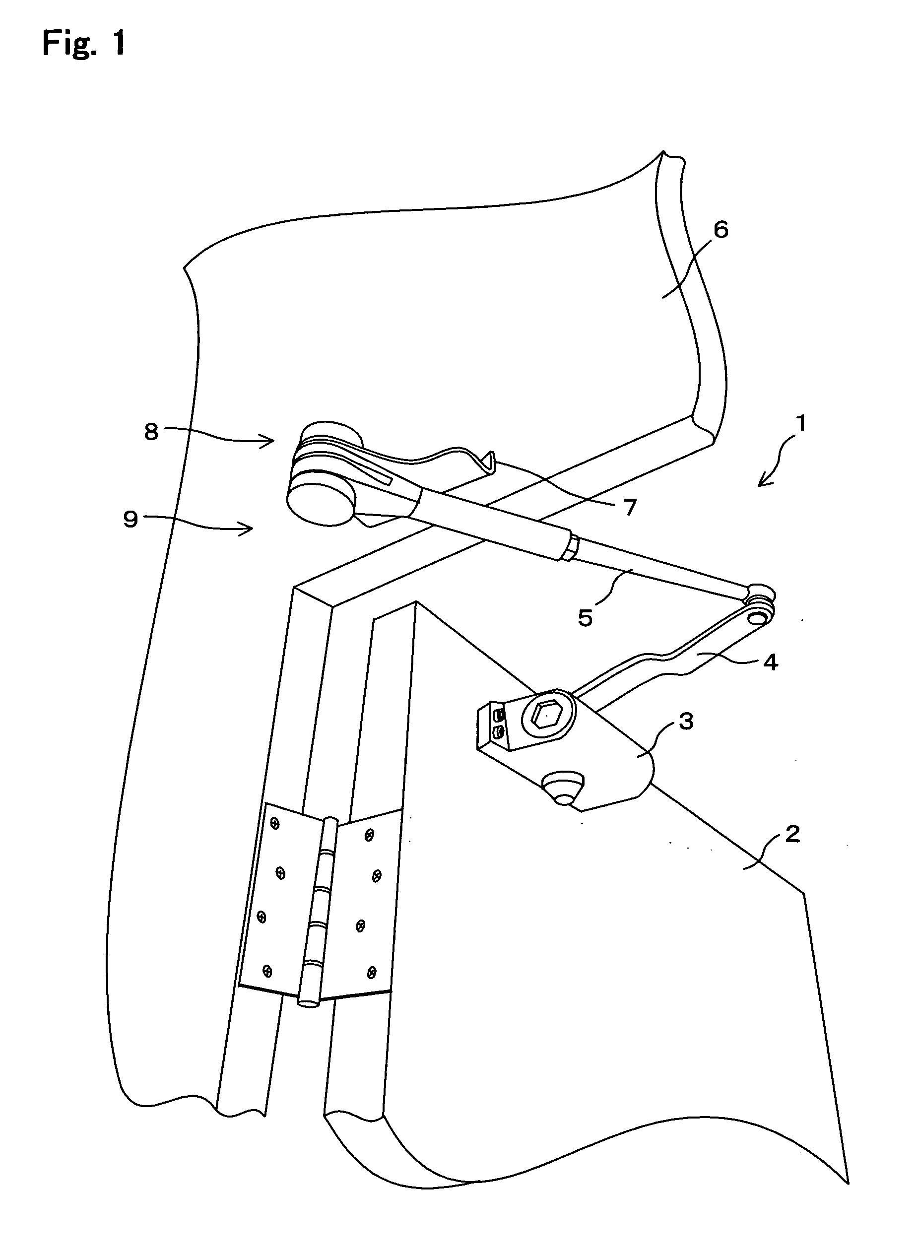
[0046]In FIG. 1, the reference numeral 1 indicates a door closer according to the present invention, and the door closer 1 includes: a door-closer main body 3 according to the present invention, installed on a door 2; a lever 4 rockably pivoted by the door-closer main body 3; an arm 5 rotatably pivoted by the lever 4; and a to-wall fixing stay 7 which is attached to a wall 6 and which rockably pivotally supports the arm 5.
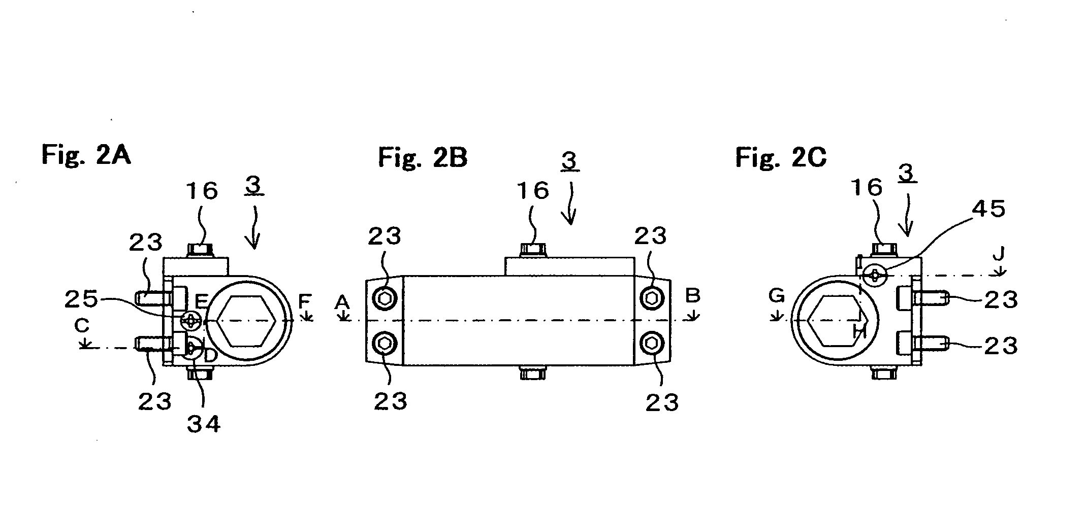
[0047]Further, the door-closer main body 3 shown in FIGS. 2A, 2B, and 2C, includes: as shown in FIGS. 3A, 3B, and 3C, a hydraulic cylinder 11; a piston 14 which is placed within the hydraulic cylinder 11 for being energized by an elastic body 12 and which is provided with a gear portion 13 formed around the periphery thereof; a gear body 15 which is pivoted by the hydraulic cylinder 11 and which engages the gear portion 13 of the piston 14 to cause the piston 14 to slide; and a restricting means 21 which temporarily restricts the rotation of the gear body 15 when t...
third embodiment
[0087]In addition, in the door-closer main body 71 it may be arranged that the lock balls 76 engage the groove 73 immediately after the door 2 is opened 90 degrees.
PUM
 Abstract
Description
Claims
Application Information