Electro-pneumatic control valve with microvalve pilot

Inactive Publication Date: 2007-11-01
MICROSTAQ
View PDF99 Cites 26 Cited by
  • Summary
  • Abstract
  • Description
  • Claims
  • Application Information

AI Technical Summary

Benefits of technology

[0006] The present invention is directed to an improved electromechanical control valve that, in one application, selectively moves a valve disk to open and close a passage between discharge and crankcase chambers of a variable capacity refrigerant compressor for purposes of controlling the compressor capacity, and a MEMS device in the form of a microvalve for selectively supplying a fluid pressure to one side of a diaphragm such that a force exerted by the fluid pressure on the diaphragm acts through the diaphragm and thence directly or indirectly upon the valve disk to selectively influence operation of the control valve. In a preferred embodiment, the electromechanical control valve further includes a sealed bellows operatively connected to the valve disk, such that the f

Problems solved by technology

If the suction pressure decreases due to a reduction in the cooling load, for example, the bellows expands to open the passage, raising the crankcase pressure and decreasing the compressor capacity.

Method used


Image

  • Electro-pneumatic control valve with microvalve pilot
  • Electro-pneumatic control valve with microvalve pilot
  • Electro-pneumatic control valve with microvalve pilot

Examples


Embodiment Construction

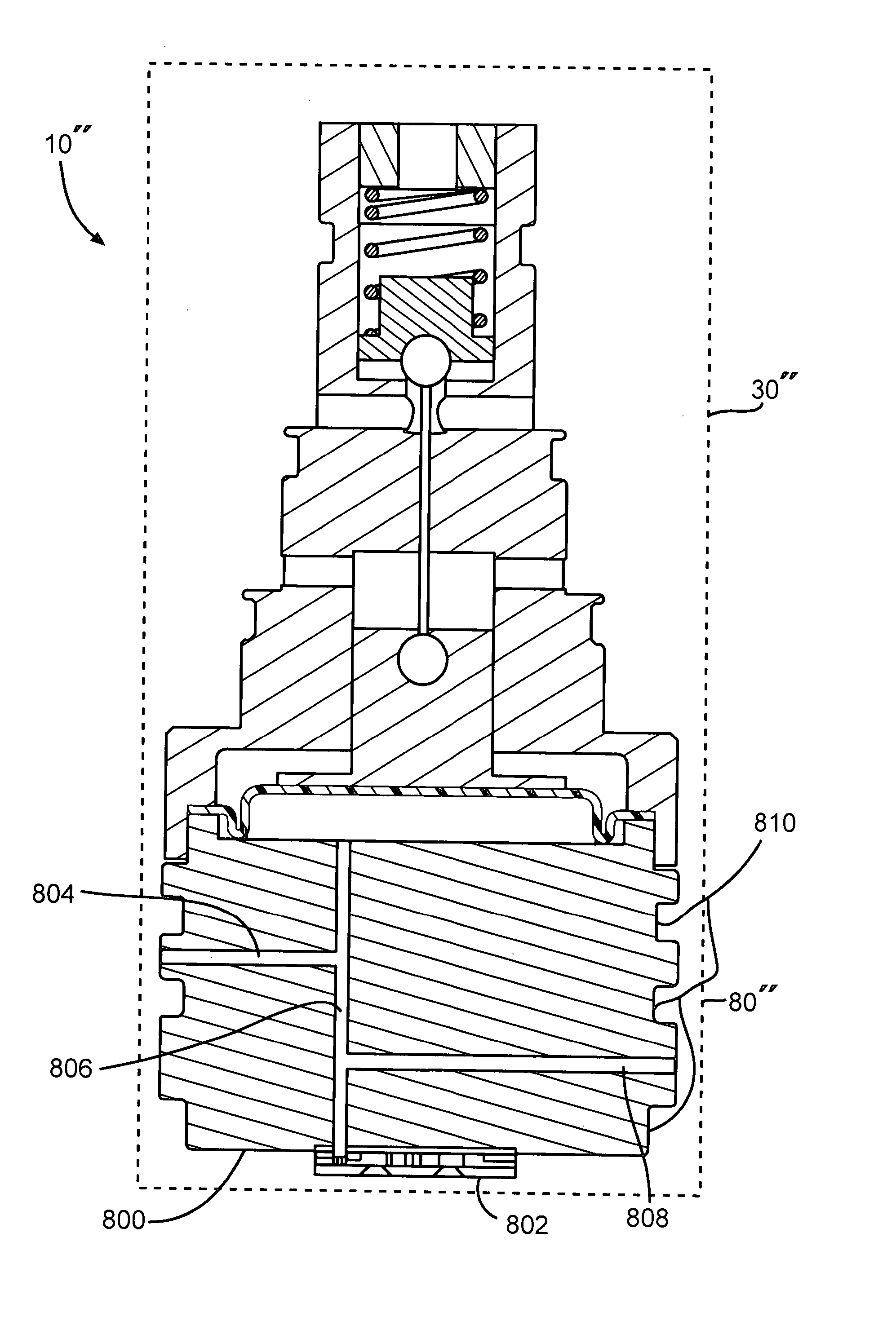
[0012]FIG. 1 illustrates a Variable set-point Control Valve (VCV) 10. The VCV 10 comprises a compressor displacement control portion 12 and a variable setpoint control portion 15. The compressor displacement control portion 12 controls the flow of refrigerant gas from a compressor (not shown) in and out of the VCV 10 while the variable setpoint control portion 15 controls the operation of the compressor displacement control portion 12. The displacement control portion 12 includes a valve body 17 is formed with many VCV functional elements, which will be described later. In the embodiment illustrated in FIG. 1, the valve body 17 is substantially cylindrical in shape as may be inferred from the cross-sectional view shown. 0-ring retaining grooves 18 are indicated on the exterior of the valve body 17 in two locations. When the VCV 10 is inserted into a control valve cavity of a compressor, it is assembled with o-ring seals (not shown) in the grooves 18 to allow different pressure sourc...


PUM


Abstract

The invention relates to a MEMS (Micro Electro Mechanical Systems) device in the form of a pressure control valve suitable for controlling the operation of a refrigeration compressor. The pressure control valve is responsive to a reference pressure controlled by a microvalve.

Description

CROSS-REFERENCE TO RELATED APPLICATIONS [0001] This application is a Continuation-In-Part of U.S. patent application Ser. No. 11 / 437,022 (filed May 18, 2006), which was a Continuation of PCT / US04 / 395 17 (filed Nov. 24, 2004), which claims priority from both U.S. Provisional Application 60 / 559,355 (filed Apr. 2, 2004, expired) and U.S. Provisional Application 60 / 525,224 (filed Nov. 24, 2003, expired). The disclosures of all four of these applications are incorporated herein by reference.STATEMENT REGARDING FEDERALLY SPONSORED RESEARCH OR DEVELOPMENT [0002] This invention was made with United States Government support under cooperative agreement number 70NANB2H10A03 awarded by the National Institute of Standards and Technology (NIST). The United States Government has certain rights in the invention.FIELD OF THE INVENTION [0003] This invention relates to a device suitable for use to control a variable capacity refrigerant compressor, and more particularly to an electro-pneumatic contro...

Claims


Application Information

Patent Timeline
IPC IPC(8): F15B5/00
CPCF04B27/1804F04B2027/1827F04B2027/1831F04B2027/1854F16K99/0001F16K2099/009F16K99/0034F16K99/0044F16K99/0059F16K2099/008F16K99/0011Y10T137/87209
Inventor FULLER, EDWARD NELSONLUCKEVICH, MARK
Owner MICROSTAQ
Why Eureka
Try Eureka