
Transreflective liquid crystal display

Inactive Publication Date: 2007-11-01
FUJIFILM CORP
View PDF11 Cites 27 Cited by
  • Summary
  • Abstract
  • Description
  • Claims
  • Application Information

AI Technical Summary

Benefits of technology

[0080] The hybrid-alignment retardation layer, which can be used in the invention, is a layer in which liquid crystal molecules are fixed in a hybrid-alignment state. In the hybrid alignment state, the tilt angles of liquid crystal molecules at an upper-side interface and at a downside interface are different each other; and, in particular, the difference between the tilt angles found at the upper-side interface and at the downside interface of the layer is equal to or more than 5°. It is preferable that the tilt angle varies continuously from one interface to another interface of the layer. There are two embodiments of the hybrid-alignment, in one of which the tilt angle increases along a direction going from the substrate-side interface to another interface, and in another of which the tilt angle decreases along a direction going from the substrate-side interface to another interface. Both can bring about the effect of the invention, and be employed in the invention. Regarding to rod-like liquid crystal molecules, the absolute value of the mean tilt angle preferably ranges from 10° to 55°, more preferably from 20° to 45°, and much more preferably from 25° to 40°. On the other hand, regarding to discotic liquid crystal molecules, the absolute value of the mean tilt angle preferably ranges from 35° to 85°, more preferably from 40° to 80°, and much more preferably from 45° to 70°. When a hybrid-alignment retardation layer with a mean tilt angle falling without the preferable range is employed in the invention, the contrast may sometimes decrease or the viewing angle range generating the gray-scale inversion may sometimes expand.
[0081] It is to be noted that a mean tilt angle can be measured according to a modified crystal rotation method.
[0082] It is also to be noted that, according to the invention, the hybrid-alignment retardation layer is not required to comprise a liquid crystal compound although it is produced by using a liquid crystal compound. In the layer, liquid crystal molecules are fixed in a state by polymerization or the like, and may lose their liquid crystallinity.
[0083] It is also to be noted that the hybrid-alignment retardation layer has no optical axis as a whole since the directors of liquid crystal molecules are random in any positions of the thickness direction.
[0084] The hybrid-alignment retardation layer can be produced by stabilizing nematic liquid crystal molecules in a hybrid alignment state with a mean tilt angle falling within the above mentioned range. The material and the stabilizing process employed in producing the retardation layer is not limited. For example, the retardation layer can be produced according to the method comprising aligning low-molecular weight liquid crystal in a hybrid alignment state and stabilizing the hybrid alignment by photo-crosslinking or thermal-crosslinking. The retardation layer can also be produced according to the method comprising aligning high-molecular weight liquid crystal in a hybrid alignment state and stabilizing the hybrid alignment by cooling.
[0085] The hybrid-alignment retardation layer may be produced by using smectic liquid crystal. For example, the hybrid-alignment retardation layer can be produced according to the method comprising aligning smectic liquid crystal in a homogenous horizontal alignment state, and transferring the homogenous alignment to a hybrid alignment while stabilizing the alignment by photo-crosslinking or thermal-crosslinking. This mechanism can be explained as follows:

Problems solved by technology

And such a conventional transreflective type LCD also suffers from narrow viewing angle property.
However, it is very difficult to produce the retardation films uniformly and to reduce light scattering.
And it is also difficult to balance the improvement in viewing angle property and the improvement in light use efficacy.

Method used


Image

  • Transreflective liquid crystal display
  • Transreflective liquid crystal display
  • Transreflective liquid crystal display

Examples


example 1 to 8

(Method for Preparing Black Photosensitive Composition for Producing Barrier Wall)

[0151] A black photosensitive composition K1 was obtained by firstly weighing a K pigment dispersion 1 and propylene glycol monomethyl ether acetate in an amount listed in Table 1, which were mixed at a temperature of 24° C. (2° C.) to be stirred at 150 RPM for 10 minutes, and then weighing methyl ethyl ketone, a binder 2, hydroquinone monomethyl ether, a DPHA liquid, 2,4-bis(trichloromethyl)-6-[4′-(N,N-diethoxycarbonylmethylamino)-3′-bromophenyl]-s-triazine and a surfactant 1 in an amount listed in Table 1, which were added in this order at a temperature of 25° C. (2° C.) to be stirred at a temperature of 40° C. (2° C.) at 150 RPM for 30 minutes. Here, the amount listed in Table 1 is in part by mass, and the detailed composition is as follows.

TABLE 1Carbon black (Nipex 35, manufactured by Degussa)13.1%Dispersant (undermentioned Compound 1)0.65%Polymer (random copolymer of6.72%benzyl methacrylate / m...


PUM


Abstract

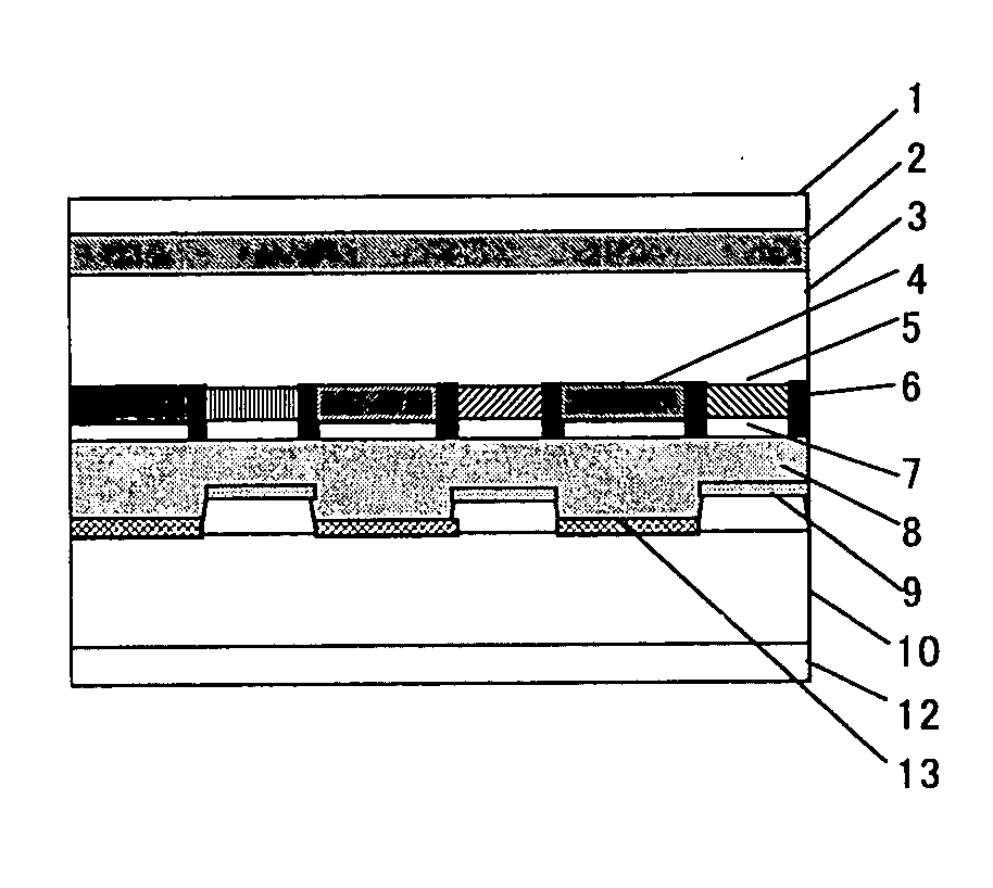
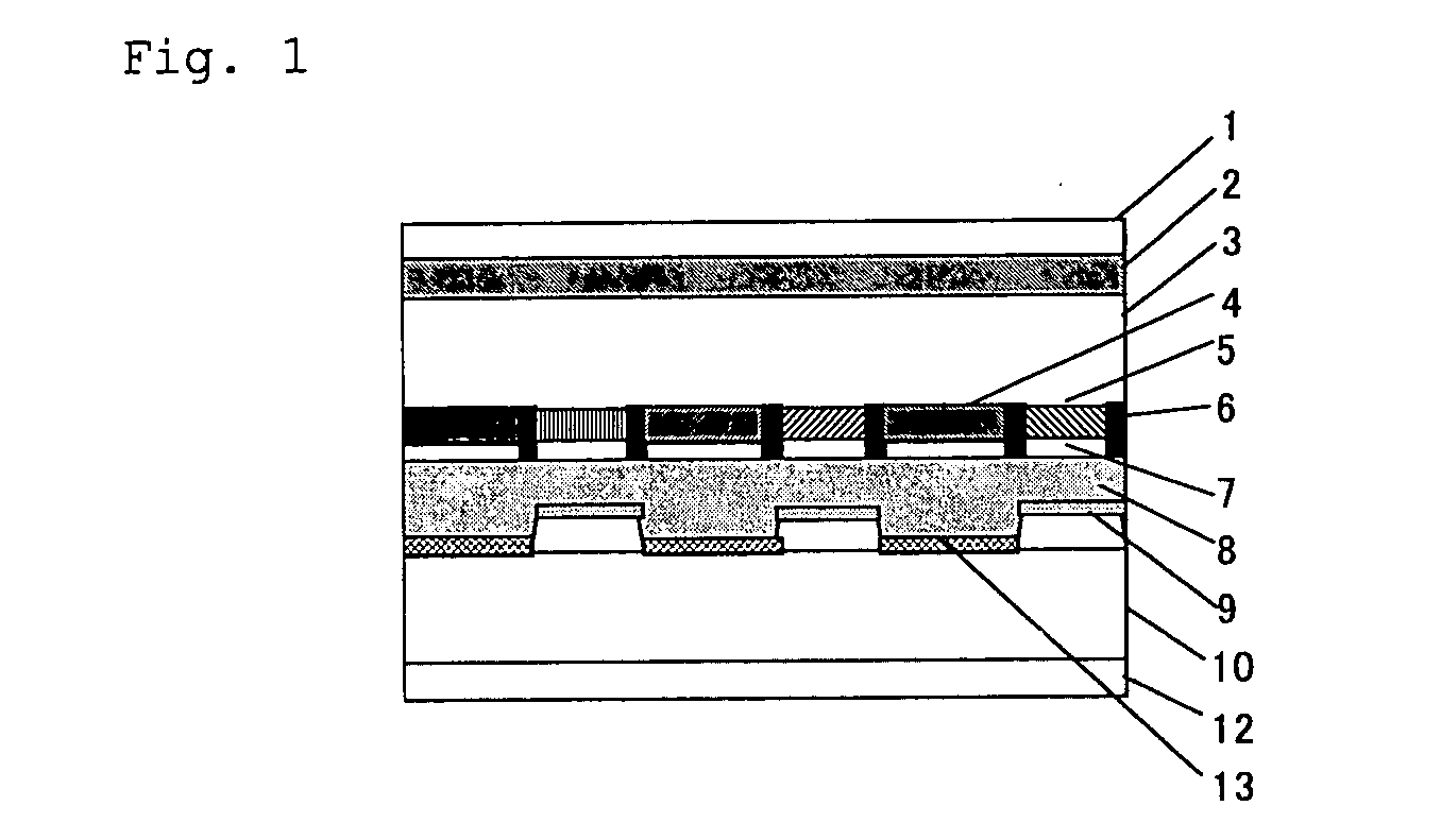
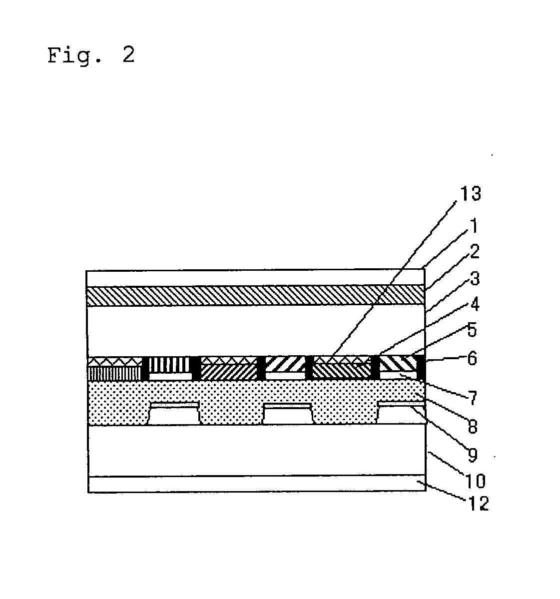
A novel liquid crystal display is disclosed. The liquid crystal display comprises a backlight, a pair of substrates, a liquid crystal layer disposed between the pair of substrates, a color filter, reflective portions, transmissive portions, and a retardation layer disposed between the pair of substrates in each of the transmissive portions. The retardation layer comprises a liquid crystal material fixed in a hybrid state, and the retardation layer has a retardation which varies depending on a wavelength of the color filter.

Description

[0001] This application claims benefit of priority under 35 U.S.C. 119 to Japanese Patent Application No. 2006-065881 filed Mar. 10, 2006. BACKGROUND OF THE INVENTION [0002] 1. Field of the Invention [0003] The present invention relates to liquid crystal displays such as transreflective and semi-transmissive liquid crystal displays to be employed in various office automation equipments, portable game machines, mobile phones and mobile terminals. [0004] 2. Related Art [0005] The liquid crystal display (LCD) technology includes major three types, the transmissive type capable of displaying images in a transmissive mode, the reflective type capable of displaying images in a reflective mode, and the transreflective type capable of displaying images in both of transmissive and reflective modes. The LCDs share a similar feature of having a slim and lightweight body, and have been employed widely as a display panel of notebook-size personal computers and TVs. Especially, the transreflectiv...

Claims


Application Information

Patent Timeline
IPC IPC(8): G02F1/1335
CPCG02F1/13363G02F2001/133565G02F2001/133633G02F2413/09G02F2203/09G02F2413/02G02F2001/133638G02F1/133565G02F1/133633G02F1/133638G02F1/133631
Inventor ICHIHASHI, MITSUYOSHIOKAMURA, HISASHISATO, MORIMASAMORISHIMA, SHINICHI
Owner FUJIFILM CORP
Learn More