Edge constrained optical membrane deformable mirror and method of fabricating

a technology of optical membrane and mirror, which is applied in the direction of mirrors, mountings, instruments, etc., can solve the problems of shim not fully supporting the membrane against the normal force of lap tools or shear forces, ripple effect on the mirror surface, and damage to the edge of the membrane, etc., to improve the liquid seal during lapping, reduce ripple, and increase the aspect ratio and long stroke actuator

Active Publication Date: 2007-11-01
NORTHROP GRUMMAN SYST CORP
View PDF4 Cites 0 Cited by
  • Summary
  • Abstract
  • Description
  • Claims
  • Application Information

AI Technical Summary

Benefits of technology

[0005] It is a further object of this invention to provide such an improved, edge constrained optical membrane deformable mirror and method of fabricating it which reduces ripple due to lap normal and shear forces.
[0006] It is a further object of this invention to provide such an improved, edge constrained optical membrane deformable mirror and method of fabricating it which improves the liquid seal during lapping, grinding or polishing.
[0007] It is a further object of this invention to provide such an improved, edge constrained optical membrane deformable mirror and method of fabricating it which enables higher aspect ratio and long stroke actuators.
[0008] It is a further object of this invention to provide such an improved, edge constrained optical membrane deformable mirror and method of fabricating it which enables larger inter-actuator or relative actuator stroke.
[0009] It is a further object of this invention to provide such an improved, edge constrained optical membrane deformable mirror and method of fabricating it which enables thinner, more flexible membranes and higher accuracy finishes.
[0012] The invention results from the realization that an improved deformable mirror with reduced ripple due to lap normal and shear forces, better sealing with higher actuator aspect ratio and stroke, higher inter-actuator stroke and thinner more flexible membrane and / or higher accuracy finishes can be achieved by applying an optical membrane across a plurality of actuators and at least a portion of a support structure which carries and surrounds at least partially, the actuators, the membrane including a first area bonded to the actuators, a second area bonded to the support structure and an intermediate area elastically decoupling the first and second areas of the optical membrane.

Problems solved by technology

Numerous problems occur: there can still be leakage; the edge of the membrane can be vulnerable to damage by the lap tool.
In addition, the shim does not fully support the membrane against the normal force of the lap tool or the shear force of the lap tool as it moves around the mirror surface.
These forces can result in a ripple effect in the mirror surface.
If the shim is made more stiff or the membrane is edge constrained more rigidly the rippling is reduced but, when the clamping force is released and the membrane relaxes the mirror surface loses the surface accuracy previously achieved and more polishing is necessary.
Further, even with the best sealing, some lapping liquid leaks can occur and the absorption of the liquid by the actuator material and the bonding agent causes changes in dimensions.
Thus, a membrane which appears to have been polished to the desired finish may, after having dried out after a few hours or days off the grinding machine, lose that finish and have to be polished again and again until the optimum result is obtained.
The lapping action to obtain the desired finish also imposes constraints on the deformable mirror design parameters.
If the actuators are not stiff enough the finish will be rippled.

Method used


Image

  • Edge constrained optical membrane deformable mirror and method of fabricating
  • Edge constrained optical membrane deformable mirror and method of fabricating
  • Edge constrained optical membrane deformable mirror and method of fabricating

Examples


Embodiment Construction

[0032] Aside from the preferred embodiment or embodiments disclosed below, this invention is capable of other embodiments and of being practiced or being carried out in various ways. Thus, it is to be understood that the invention is not limited in its application to the details of construction and the arrangements of components set forth in the following description or illustrated in the drawings. If only one embodiment is described herein, the claims hereof are not to be limited to that embodiment. Moreover, the claims hereof are not to be read restrictively unless there is clear and convincing evidence manifesting a certain exclusion, restriction, or disclaimer.

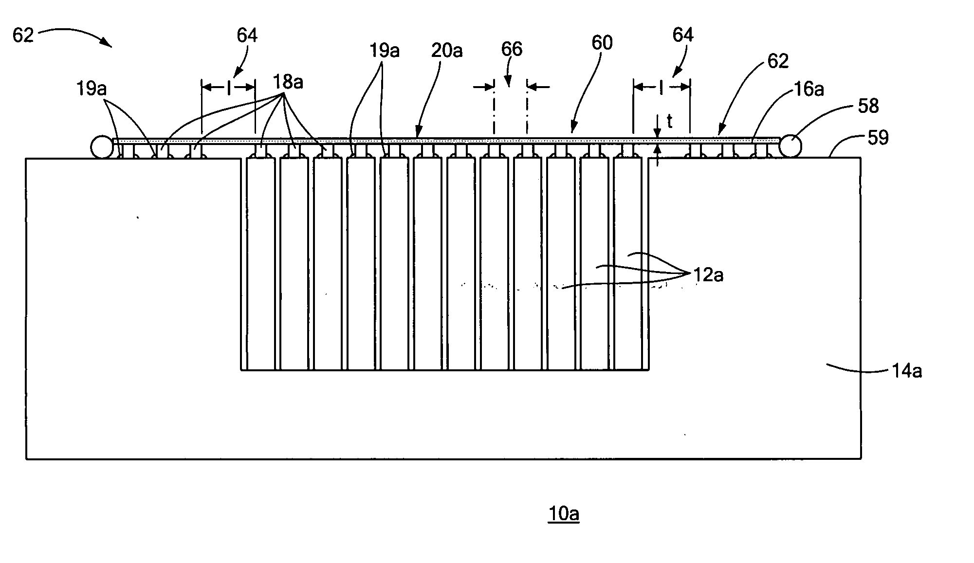
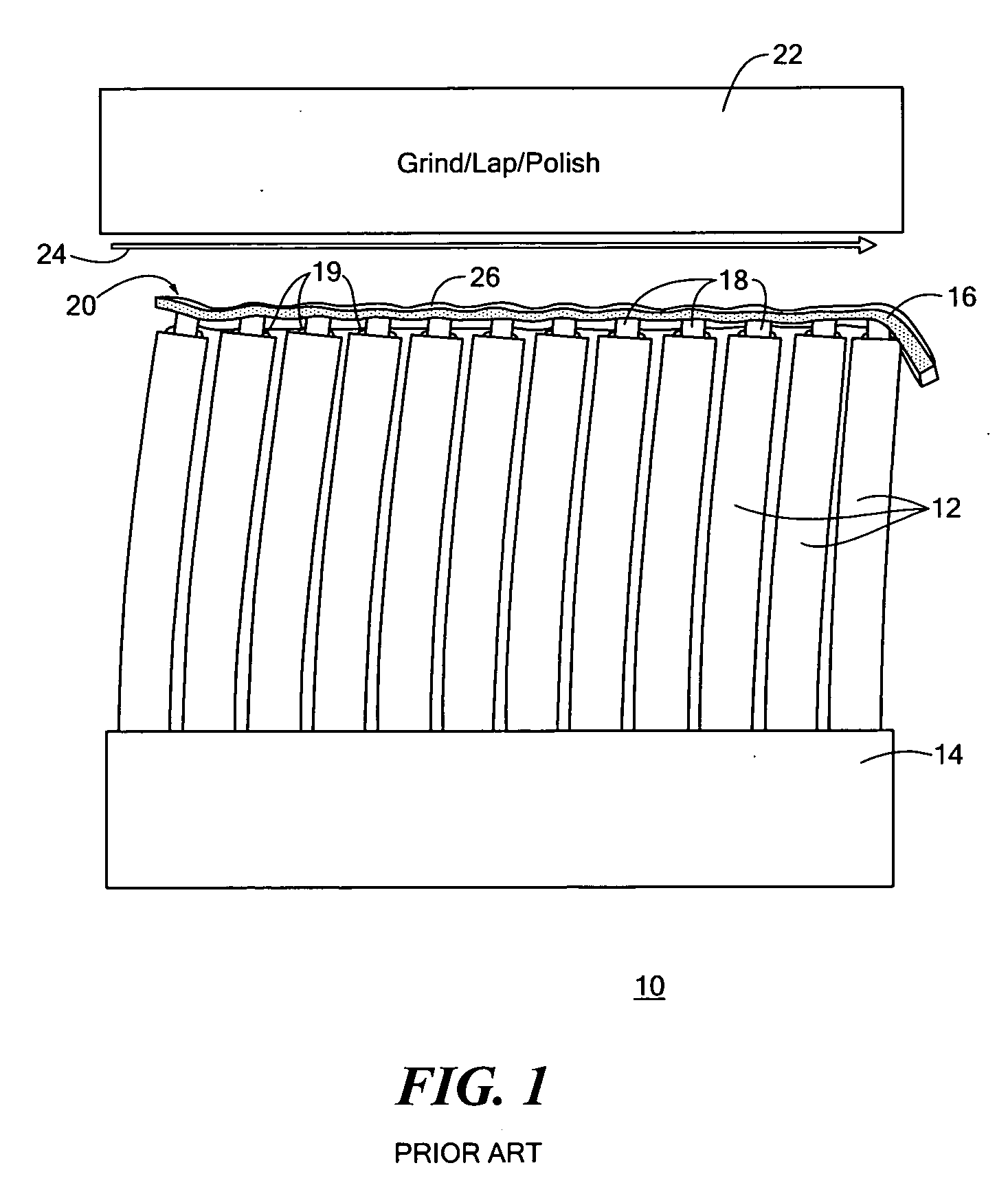
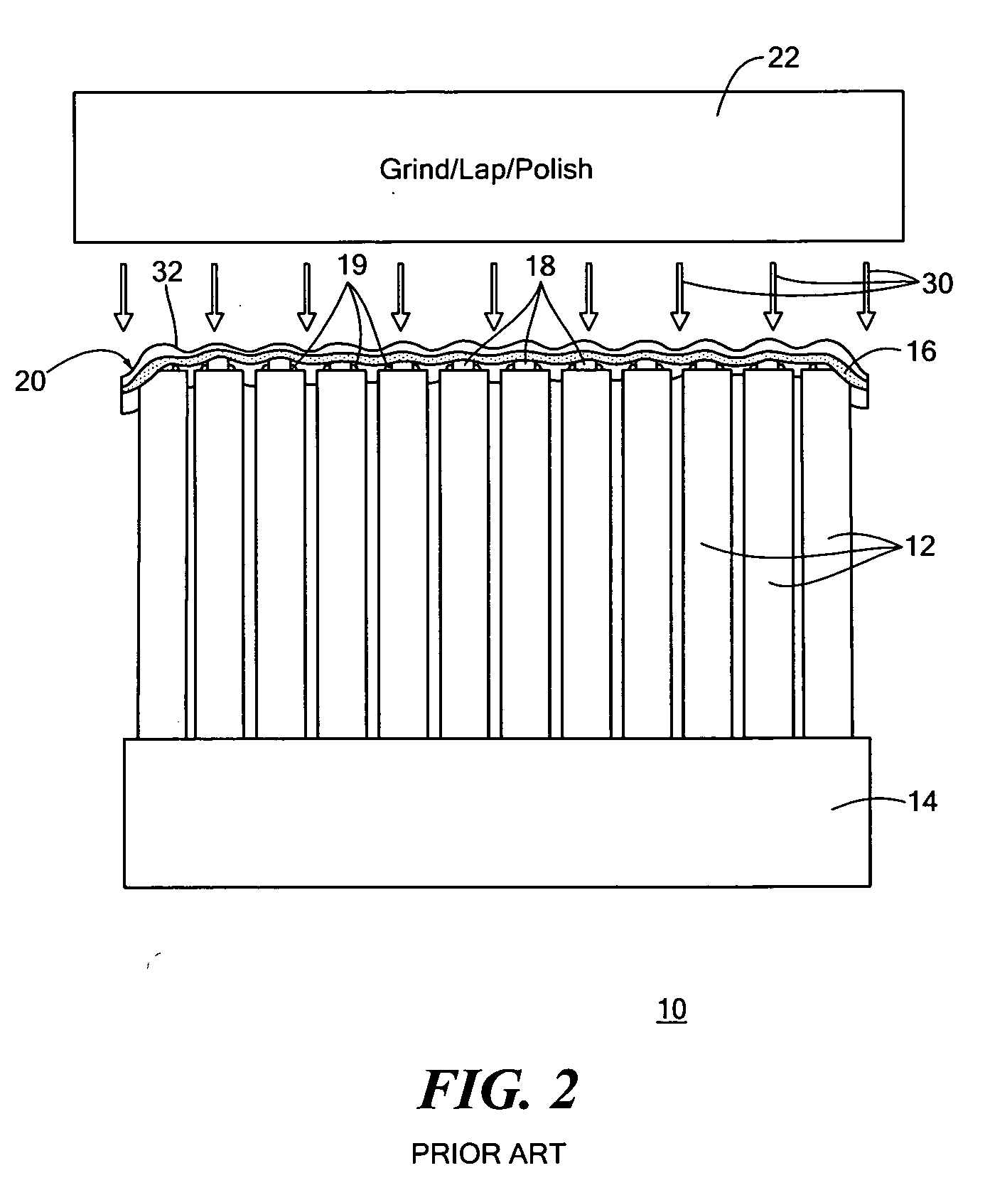
[0033] There is shown in FIG. 1, a prior art deformable mirror 10 including a plurality of actuators 12 mounted on base 14 and carrying a face sheet or optical membrane 16 with pusher pads 18 bonded to the tops of actuators 12 by some bonding medium 19 such as epoxy. To obtain a desired mirror finish on mirror surface 20 ...


PUM


Abstract

Fabricating a deformable mirror by providing a plurality of actuators and a support structure supporting and at least partially surrounding the actuators; applying an optical membrane across the actuators and at least a portion of the support structure; the optical membrane including a first area, a second area and an intermediate area elastically decoupling the first and second areas; bonding the first area to the actuators and the second area to the support structure; and polishing the optical membrane.

Description

FIELD OF THE INVENTION [0001] This invention relates to an edge constrained optical membrane deformable mirror and method of fabricating it. BACKGROUND OF THE INVENTION [0002] Deformable mirrors employ a face sheet or optical membrane carried by a plurality of actuators that can be individually operated to provide micro and macro adjustment of the mirror surface. The optical membrane typically has a plurality of regularly spaced pads on its bonding surface which are bonded to the actuators using a bonding medium such as epoxy. After bonding the mirror surface of the membrane is lapped or polished to obtain a desired mirror finish. Lapping or polishing is typically a wet process using any of a number of different liquids which may be e.g., acid, or alkaline, etching or not-etching. During polishing shims can be used between the membrane and a holding jig to seal the actuators, pads and bonding agent from the liquid. Numerous problems occur: there can still be leakage; the edge of the...

Claims


Application Information

Patent Timeline
Patent Type & Authority Applications(United States)
IPC IPC(8): G02B5/08
CPCG02B26/0825
Inventor CAVACO, JEFFREY L.WELLMAN, JOHN A.
Owner NORTHROP GRUMMAN SYST CORP
Why Eureka
Try Eureka