

Automatically Quenching Surge Arrester Arrangement and Use of Such a Surge Arrester Arrangement
a surge arrester and automatic quenching technology, applied in the field of electric protection, can solve the problems of changing the operation of the voltage resistor, permanent damage to the electrical device or to a total failure, and interrupting the current flow through the varistor
- Summary
- Abstract
- Description
- Claims
- Application Information
AI Technical Summary
Benefits of technology
Problems solved by technology
Method used
Image

Examples
Embodiment Construction
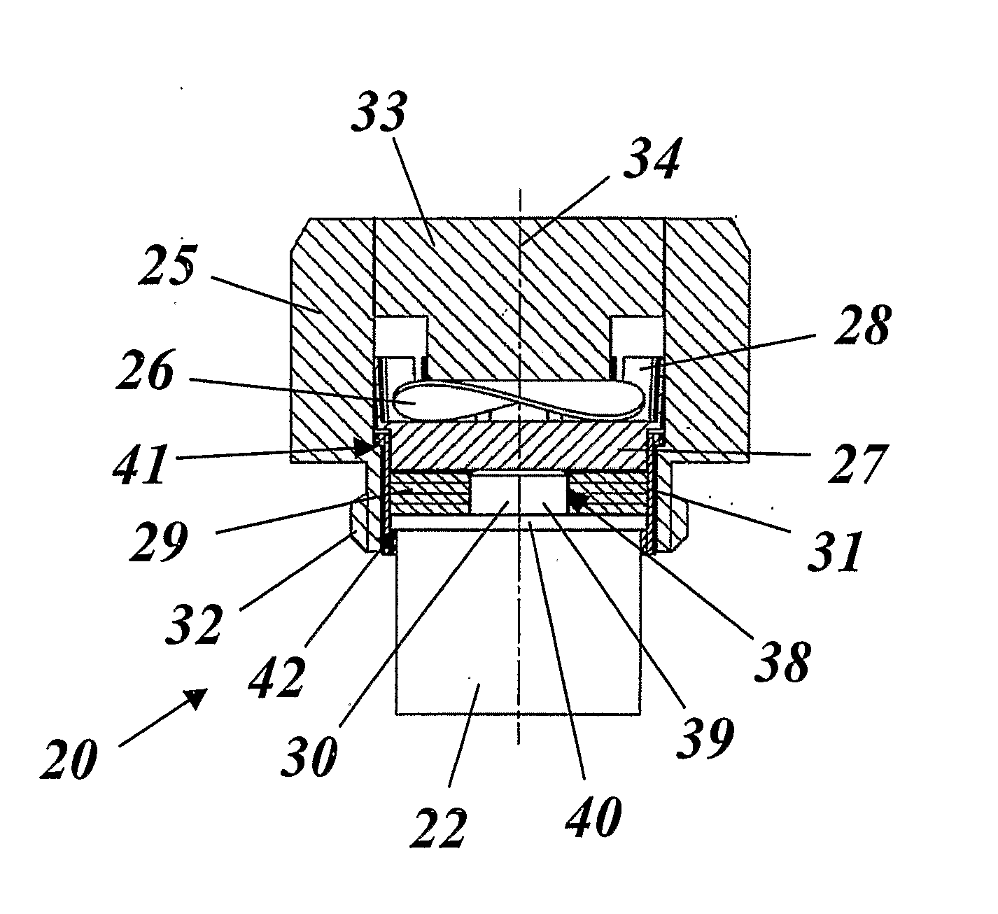
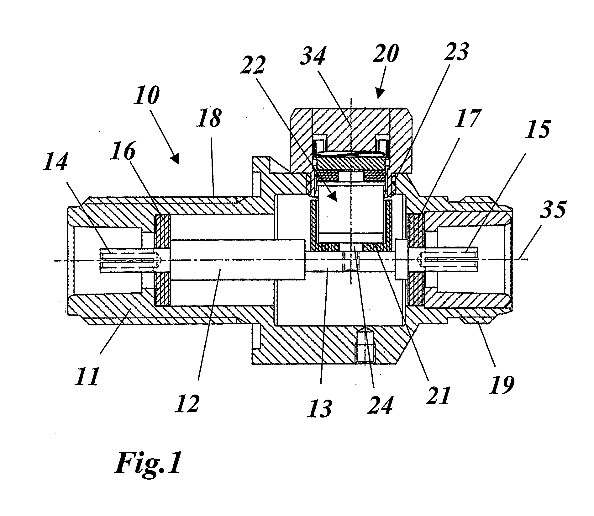
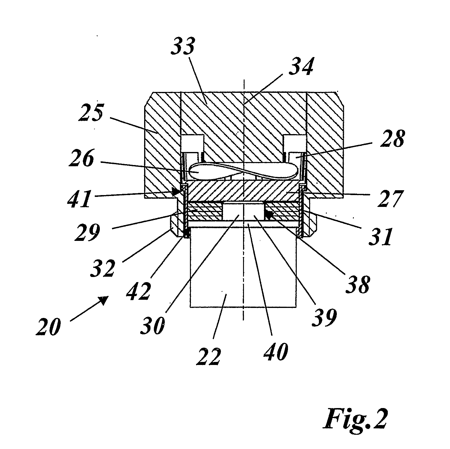
[0010] The object of the invention is thus to create an automatically quenching, broad bandwidth and low-cost surge arrester arrangement, which is of simple and robust design, is highly functionally reliable, can be implemented in an extremely space-saving manner, and in particular can be retrofitted to existing coaxial conductor applications without physical modifications.
[0011] This is achieved by the totality of the features of claim 1. The essence of the invention is to provide a switching mechanism which responds reversibly to the heat which is produced by the current flow through the surge arrester when a current flows through the surge arrester and interrupts the current flow through the surge arrester, and then automatically returns to its initial state again. In the simplest case, this can be achieved by purely electronic means, for example by using a resistor with a positive temperature coefficient (PTC) or a negative temperature coefficient (NTC) to monitor the heat in t...
PUM
 Abstract
Description
Claims
Application Information