
Fuel supply device

a technology of fuel supply and heat sink, which is applied in the direction of positive displacement liquid engines, combustion-air/fuel-air treatment, piston pumps, etc., can solve the problems of difficult positioning of heat sinks and the inability to cool control units, and achieve the effect of increasing the capacity and surface area of heat sinks

Inactive Publication Date: 2007-11-01
AISAN IND CO LTD
View PDF3 Cites 16 Cited by
  • Summary
  • Abstract
  • Description
  • Claims
  • Application Information

AI Technical Summary

Benefits of technology

[0008]It is, accordingly, one object of the present teachings to provide a fuel supply device, in which a heat sink with a high radiating performance can be arranged without enlarging the fuel supply device.
[0010]In this apparatus, the extended portion of the heat sink functions as a guide member. By making the extended portion of the heat sink function as the guide member, a heat sink that has a larger capacity and the larger surface area can be disposed within the apparatus without enlarging the apparatus itself. Consequently, heat generated in the control unit can be suitably dissipated.
[0012]Such a structure of the apparatus enables the dissipation of heat from the leading edge of the extended portion into the fuel in the reserve cup. Since the fuel in the reserve cup has a lower temperature, compared with the heat sink, the heat dissipates from the leading edge of the extended portion into the fuel. Consequently, the control unit is more effectively cooled.
[0014]Such a structure of the apparatus can prevent axial rotation of the fuel discharging unit relative to the extended portion of the heat sink. Consequently, the fuel discharging unit can be accurately disposed.
[0016]In this fuel supply device, the extended portion of the heat sink functions as a guide member. Consequently, the capacity and surface area of the heat sink can be increased without enlarging the device itself.

Problems solved by technology

Therefore, when no fuel is discharged from the fuel discharging unit, the control unit cannot be cooled because no fuel flows through the cooling passage.
This consequently makes it difficult to position a heat sink, with a high radiating performance (e.g., a heat sink having a large surface area), in the fuel supply device.

Method used


Image

  • Fuel supply device
  • Fuel supply device
  • Fuel supply device

Examples


embodiment

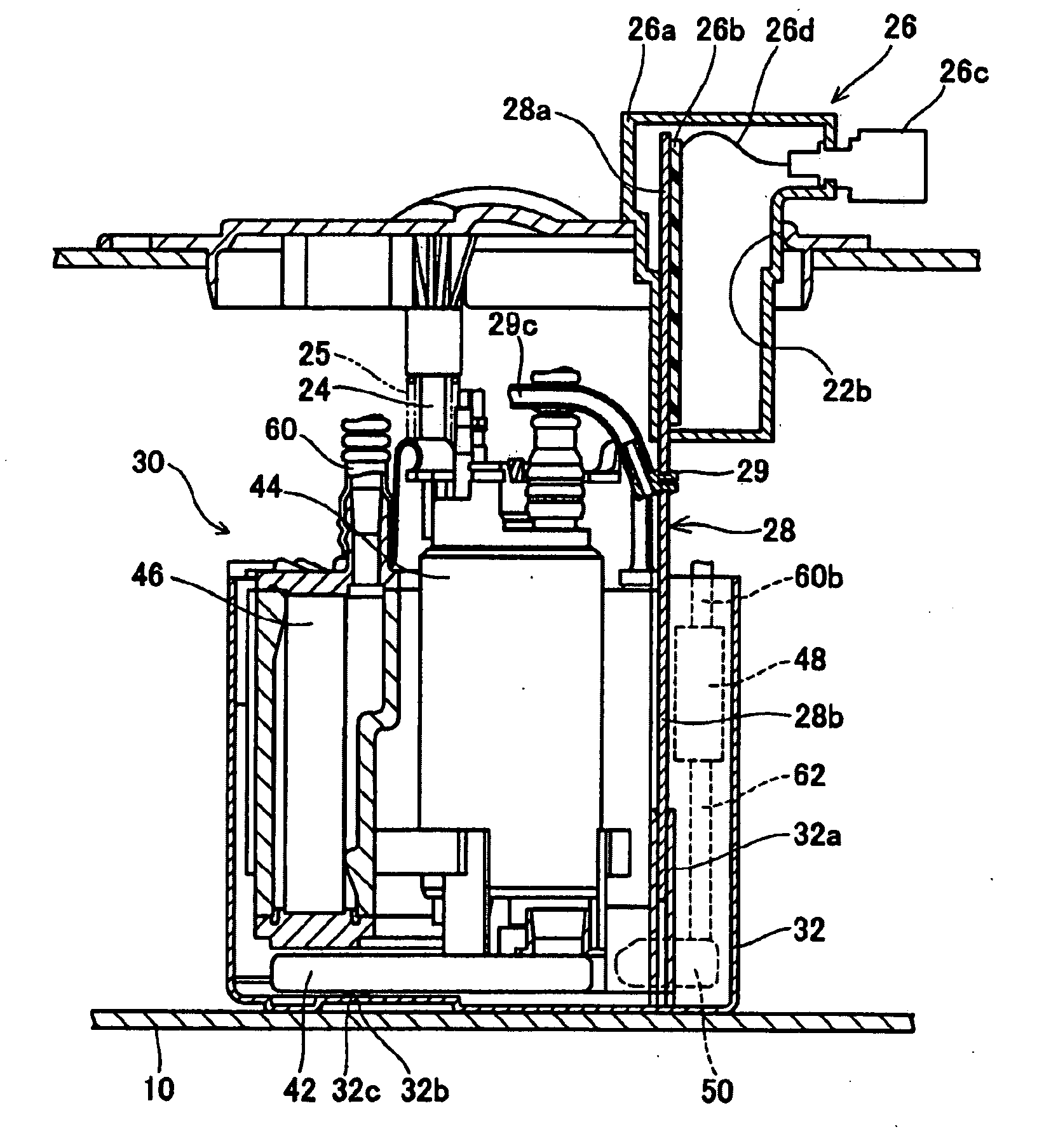
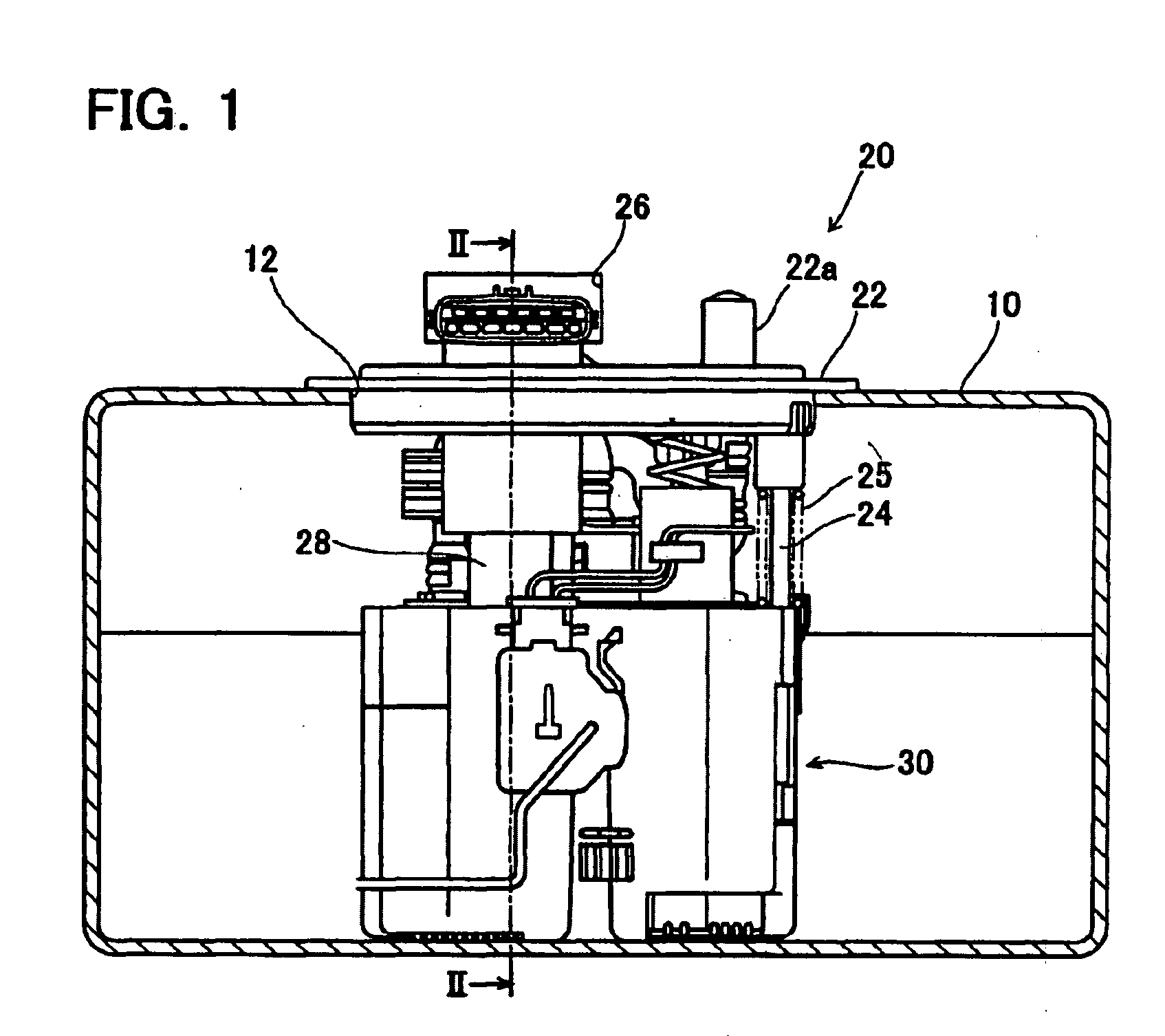
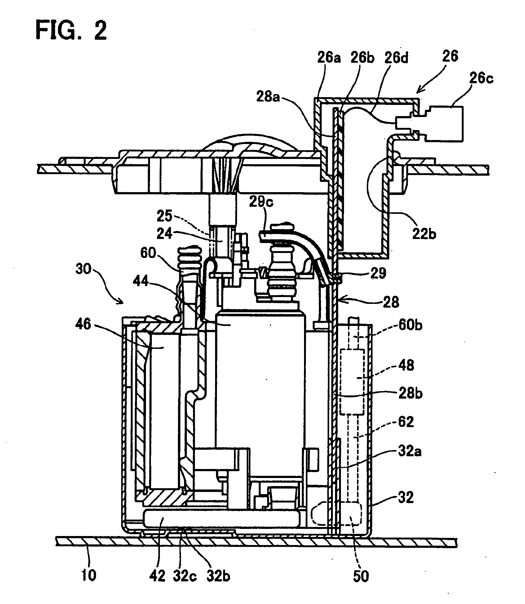
[0033]A fuel supply device 20 according to this preferred embodiment of the present teachings will be described in reference to the accompanying drawings. As shown in FIG. 1, the fuel supply device 20 is used when attached to a fuel tank 10 of an automobile or the like. The fuel supply device 20 draws fuel from within the fuel tank 10 and supplies the drawn fuel to an engine of the automobile or the like. The fuel supply device 20 comprises a cover 22, a guide 24, a fuel discharging unit 30, a spring 25, a controller 26 and a heat sink 28.

[0034]The cover 22 is attached to the fuel tank 10 so as to close an opening 12 formed in an upper portion of the fuel tank 10. The cover 22 includes a fuel discharge port 22a. One end of a fuel supply pipe, not shown, for supplying fuel to the engine is connected to the upper end of the fuel discharge port 22a. A pipe 60 of the fuel discharging unit 30 is connected to the lower end of the fuel discharge port 22a. The fuel from the fuel discharging...


PUM


Abstract

An apparatus (20) may comprise a fuel tank (10), a cover (22), a fuel discharging unit (30), a control unit (26), and a heat sink (28). The cover (22) closes an opening (12) in an upper portion of the fuel tank (10). The fuel discharging unit (30) is disposed within the fuel tank (10), and the fuel discharging unit (30) draws fuel into the fuel tank and discharges the drawn fuel outside the fuel tank. A biasing member (25) may be disposed between the fuel discharging unit (30) and the cover (22), and bias the fuel discharging unit (30) toward the bottom surface of the fuel tank (10). The control unit (26) controls the fuel discharging unit (30). The heat sink (28) is thermally connected to the control unit (26), and dissipates heat from the control unit (26). The heat sink (28) may include an extended portion (28b) extending in an up-down direction in the fuel tank (10). The fuel discharging unit (30) may be slidably supported by the extended portion (28b).

Description

CROSS-REFERENCE TO RELATED APPLICATION[0001]This application claims priority to Japanese Patent Application No. 2006-123424 filed on Apr. 27, 2006, the contents of which are hereby incorporated by reference into the present application.BACKGROUND OF THE INVENTION[0002]1. Field of the Invention[0003]This invention relates to a fuel supply device for supplying fuel from a fuel tank to an external device.[0004]2. Description of the Related Art[0005]Japanese Laid-Open Patent Publication No. 2005-155602 discloses a fuel supply device. This fuel supply device comprises a cover for closing an upper opening of a fuel tank, two guide members extending in an up-down direction in the fuel tank, and a fuel discharging unit guided by these guide members so as to be vertically movable within the fuel tank. A spring is disposed between the fuel discharging unit and the cover. The spring biases the fuel discharging unit toward the bottom surface of the fuel tank. Therefore, the bottom of the fuel d...

Claims


Application Information

Patent Timeline
IPC IPC(8): F04B17/00F04B35/04
CPCF02M31/20F02M37/025Y02T10/126F02M37/106F02M2037/225F02M37/103F02M37/44Y02T10/12Y10T137/86187
Inventor SUZUKI, NOBUO
Owner AISAN IND CO LTD
Learn More