Imaging apparatus

a technology of imaging apparatus and spherical glass, which is applied in the direction of applications, instruments, optical elements, etc., can solve the problems of affecting the observation process, affecting the quality of the image, so as to prevent the occurrence of reflection, reduce the noise, and produce sharp images

Inactive Publication Date: 2007-11-01
OLYMPUS CORP
View PDF5 Cites 2 Cited by
  • Summary
  • Abstract
  • Description
  • Claims
  • Application Information

AI Technical Summary

Benefits of technology

[0007] The present invention has been made to address the above problems with the object being to provide an imaging apparatus capable of producing sharp images with low noise by preventing the occurrence of reflection at an proximal end of a small-diameter image-transmitting portion and also by avoiding autofluorescene from being produced.

Problems solved by technology

However, the flat glass plate disposed on the incident end of the small-diameter image-transmitting portion or the oil used in the space between the incident end and the objective lens brings about a drawback that autofluorescene is produced in the flat glass plate or in the oil upon incidence of illumination light on the small-diameter image-transmitting portion, in the case when the illumination light is excitation light.
An imaging apparatus containing oil also has problems that handling of oil is a cumbersome task and makes an observation procedure complicated.

Method used


Image

  • Imaging apparatus
  • Imaging apparatus
  • Imaging apparatus

Examples


first embodiment

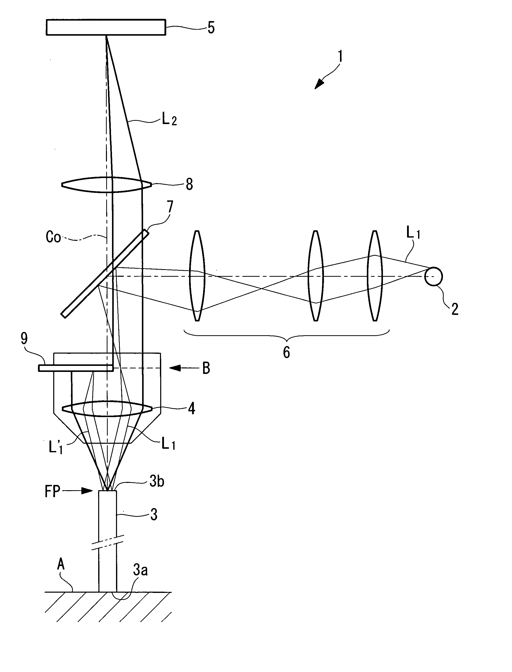
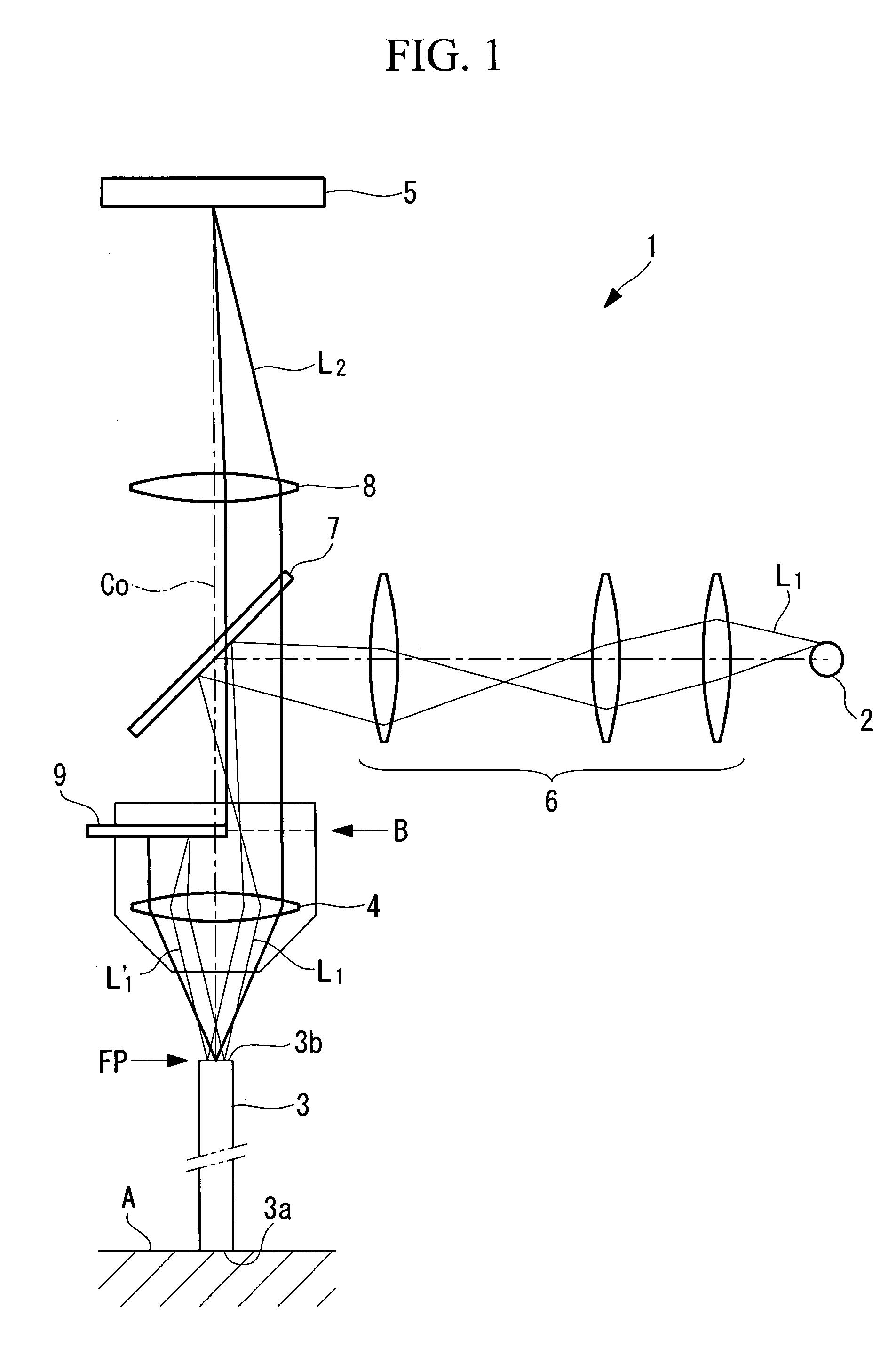
[0029] An imaging apparatus 1 according to the present invention will now be described with reference to the attached drawing, FIG. 1. The imaging apparatus 1 according to this embodiment includes, as shown in FIG. 1, a light source (illumination light source) 2 emitting excitation light (illumination light) L1, a rod lens (small-diameter image-transmitting portion) 3, the distal end 3a of which is placed near a specimen A, an objective lens 4 converging the excitation light L1 emitted from the light source 2 to the proximal end 3b of the rod lens 3, and an image pickup device (light-detecting device) 5 that detects fluorescence light L2 generated in the specimen A and returned therefrom via the rod lens 3 and the objective lens 4. The proximal end 3b of the rod lens 3 coincides with the focal plane FP of the objective lens 4.

[0030] In FIG. 1, reference numeral 6 denotes an optical illumination system, 7 denotes a dichroic mirror, and 8 denotes an image formation lens. Adding to the...

second embodiment

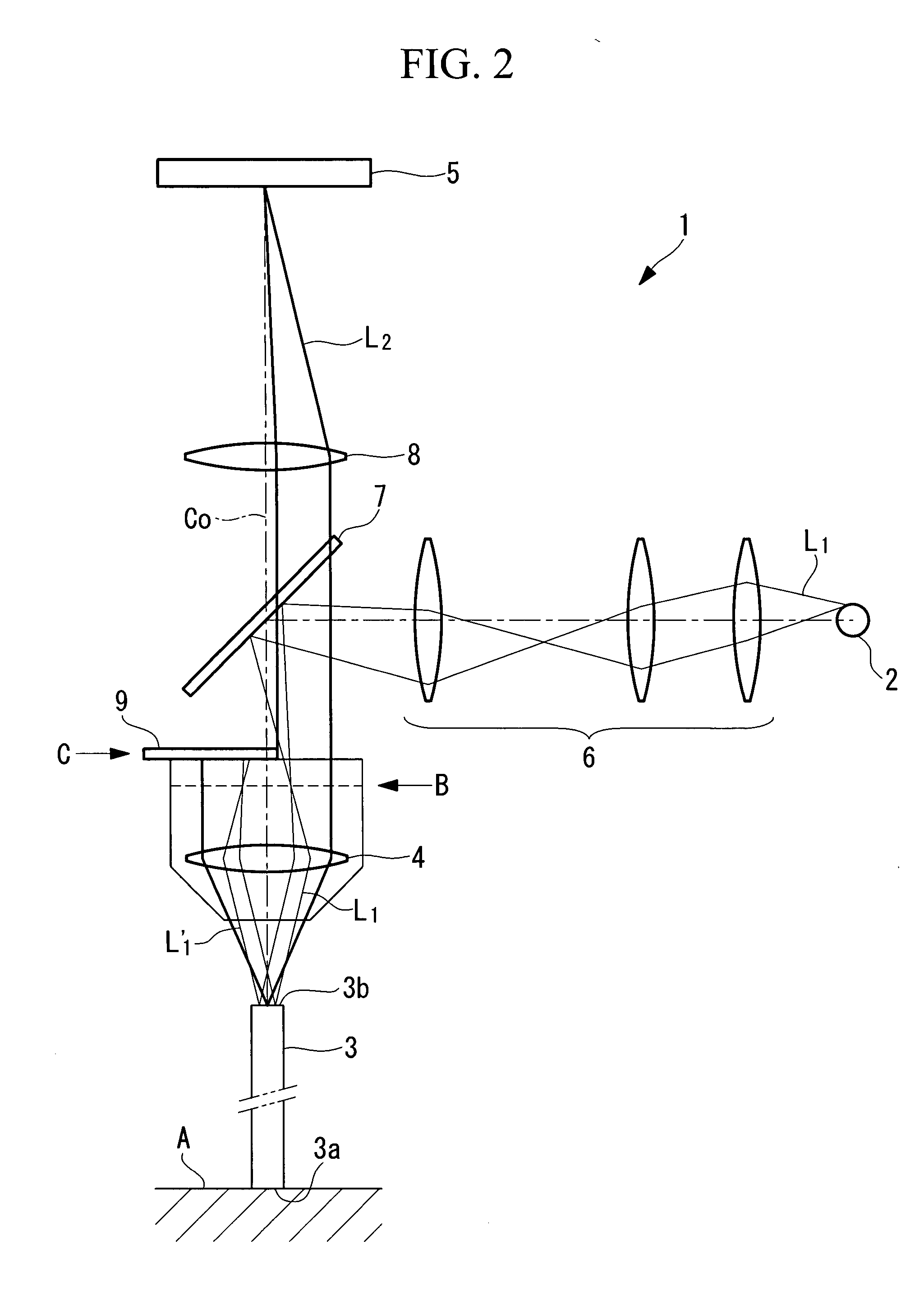
[0046] At the proximal end 11b of an imaging fiber 11, the excitation light L1 is incident from one side with respect to its optical axis and reflected toward the other side. The reflected light L1′ of the excitation light L1 reflected from the proximal end 11b returns along the same optical path via the objective lens 4, the image formation lens 27, the relay lens 25, the scanner 26 and the relay lenses 23, 24. The reflected light L1′, however, is blocked by the shield member 9 disposed at near the position B′ optically conjugate with the pupil position B of the objective lens 4 so as not to be transmitted to the side of the dichroic mirror 7. The shield member 9 disposed at the position B′ brings about the same effect as in the second embodiment, in which it is disposed at near the pupil position B.

[0047] As with the second embodiment, since the proximal end 11b of the imaging fiber 11 is inclined at a predetermined angle with respect to the plane orthogonal to the optical axis of...


PUM


Abstract

An imaging apparatus includes an illumination light source emitting illumination light, a small-diameter image-transmitting portion, a distal end of which is placed near a specimen, an objective lens converging the illumination light to a proximal end of the image-transmitting portion, a light-detecting portion that detects light returned from the specimen via the image-transmitting portion and the objective lens, and a shield portion partially blocking the illumination light, the shield portion being disposed at near a pupil position of the objective lens or near a position optically conjugate with the pupil position so as to cover the illumination light path on one side in a radial direction. With this configuration, a sharp image with low noise can be obtained by preventing the occurrence of reflection at the proximal end of the image-transmitting portion and also by avoiding autofluorescene from being produced.

Description

BACKGROUND OF THE INVENTION [0001] 1. Field of the Invention [0002] The present invention relates to an imaging apparatus, and more specifically to an imaging apparatus having a small-diameter image-transmitting portion at the forward end thereof for direct observation of an internal tissue from a living body in a medical or biological field. [0003] This application is based on Japanese Patent Application No. 2006-123587, the content of which is incorporated herein by reference. [0004] 2. Description of Related Art [0005] Examples of this type of imaging apparatus are disclosed in Japanese Translation of PCT International application, Publication No. 2005-512746 and also in the specification of U.S. Pat. No. 6,370,422. These imaging apparatuses are configured so as to eliminate a disadvantage that a portion of illumination light reflected at the incident end of a small-diameter image-transmitting portion is combined with signal light as noise, the illumination light being emitted fr...

Claims


Application Information

Patent Timeline
Patent Type & Authority Applications(United States)
IPC IPC(8): A61B6/00G01Q60/22G02B21/06
CPCG02B21/06G02B23/2469G02B23/2453
Inventor FUKUSHIMA, IKUTOSHIHIRATA, TADASHIFUJIWARA, MASATO
Owner OLYMPUS CORP
Why Eureka
Try Eureka