Liquid-mixing infusor

a technology of infusor and liquid, which is applied in the field of liquid infusor, can solve the problems of difficult preparation of a structure to prevent air from entering the body

Inactive Publication Date: 2007-11-01
KPR U S LLC
View PDF3 Cites 61 Cited by
  • Summary
  • Abstract
  • Description
  • Claims
  • Application Information

AI Technical Summary

Benefits of technology

[0007]This disclosure has been created for circumstances as described above to provide a liquid-mixing infusor making it possible to remove any air in liquids and to connect or block any optional branch tubes among a plurality of branch tubes.
[0022]Moreover, another characteristic of the liquid-mixing infusor of this disclosure is that the circumferential surface of the chamber has positioning bosses installed, and at the same time, the operation portion has stops installed to stop the valve at a specified position by allowing it to be engaged with the positioning bosses. Accordingly, the rotary portion can be reliably stopped at the specified position allowing the valve to carry out flow path switching accurately.

Problems solved by technology

Therefore, a liquid-mixing infusor to administer a plurality of normal saline or drug solutions by connecting or blocking a plurality of infusion tubes, but, in such a liquid-mixing infusor, it is difficult to prepare a structure preventing air from entering the body.

Method used


Image

  • Liquid-mixing infusor
  • Liquid-mixing infusor
  • Liquid-mixing infusor

Examples


first embodiment

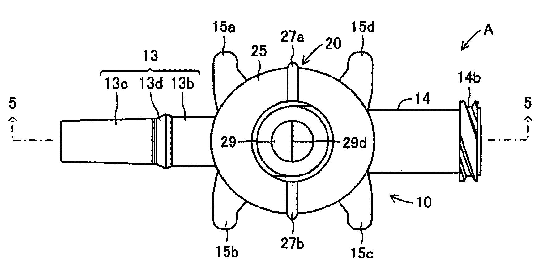
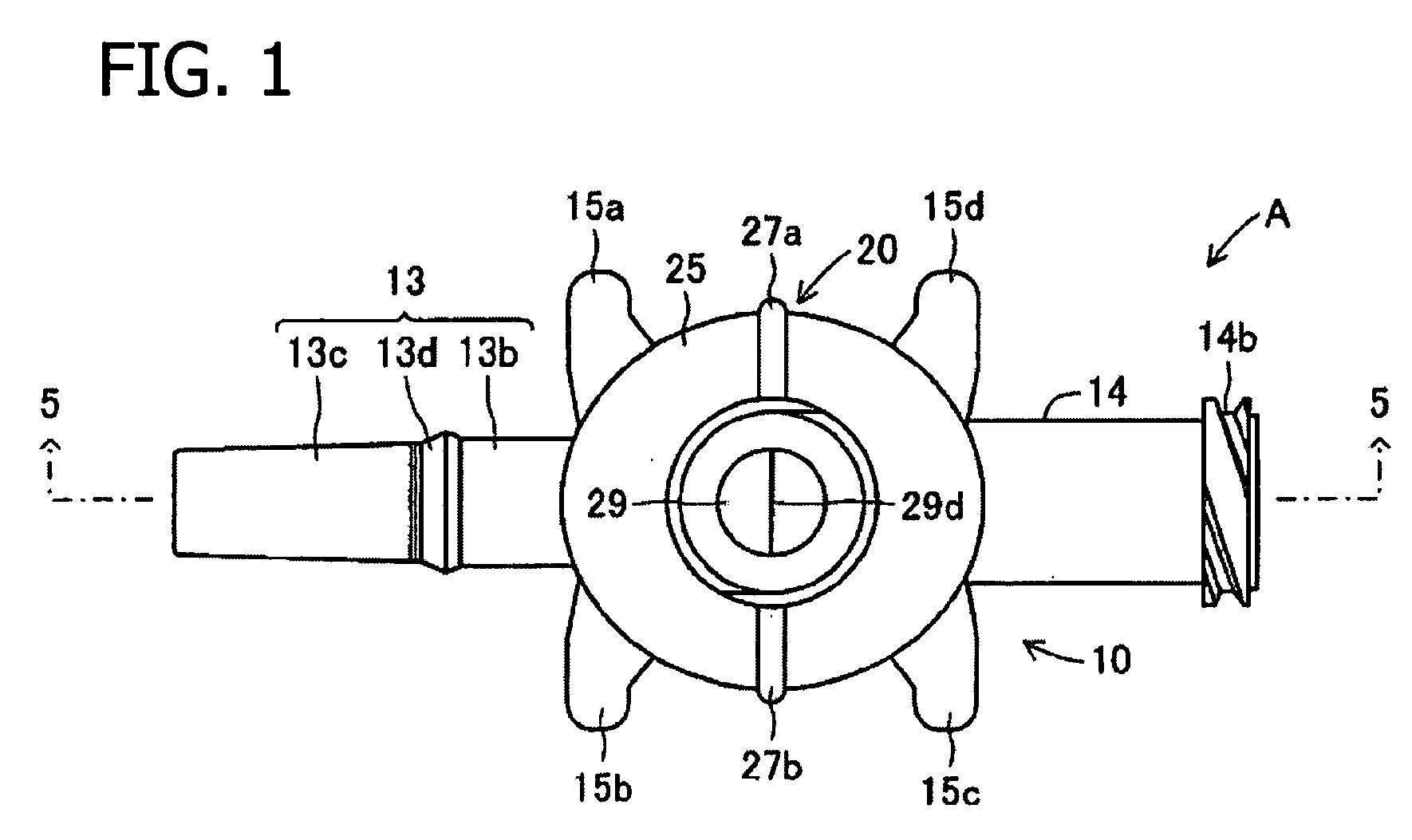
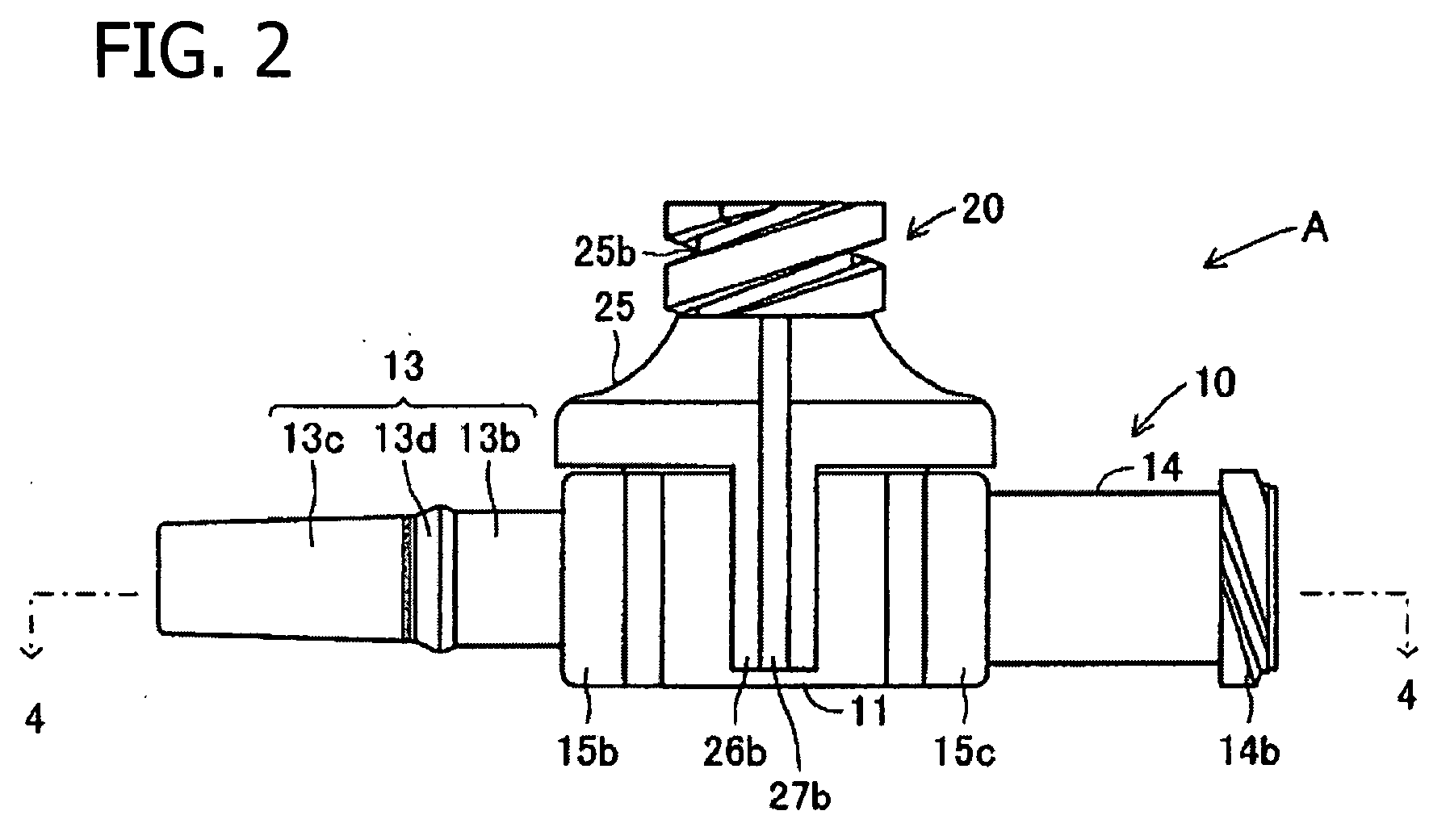
[0043]A liquid-mixing infusor as this disclosure is explained in detail by using drawings as follows. FIGS. 1-3 are drawings showing a liquid-mixing infusor A of this embodiment, and this liquid-mixing infusor A includes a liquid-mixing infusor main body 10 and rotary portion 20. The liquid-mixing infusor main body 10 includes a chamber 11 formed as a cylinder having a short length in the axial direction and vertically disposed axial direction, confluent branching portion 12 formed above the chamber 11 (see FIG. 5) and a pair of downstream and upstream branch tubes 13 and 14, respectively connected to two sides of the chamber 11 at its peripheral surface and extended coaxially maintaining an angle of 180°.

[0044]The main portion of the chamber 11 forms a bottomed cylinder with its bottom closed and top open, and on its peripheral surface in the circumferential direction, handling extrusions 15a, 15b, 15c and 15d are formed. The handling extrusions 15a, 15b, 15c and 15d extend from th...

second embodiment

[0071]FIG. 10-FIG. 12 shows a liquid-mixing infusor B of this disclosure. This liquid-mixing infusor B includes a liquid-mixing infusor main body 30 and rotary portion 40. The liquid-mixing infusor main body 30 has a chamber 31, which is a cylinder with top and bottom ends opened as shown in FIG. 13. The top end periphery of the chamber 31 has an annular catch 31a including an extrusion, and at a position slightly lower than this, catch 31a is on the inner circumferential surface of the chamber 31, and a ring shaped extrusion 32 protruding inwards is formed.

[0072]Below this extrusion 32 formed on the inner circumferential surface of the chamber 31, an annular catch 31b including an extrusion is formed, and the rotary portion 40 is installed so as to be freely rotatable on this catch 31b. Furthermore, the outer periphery of the main body portion of the chamber 31 has handling extrusions 35a, 35b, 35c and 35d formed with spacing between them in the circumferential direction. These han...

third embodiment

[0079]FIGS. 16-18 show a liquid-mixing infusor C as this disclosure. This liquid-mixing infusor C has a vertical cross section along the length direction the same as that shown in FIG. 13. In this liquid-mixing infusor C, a valve 51 is formed in a roughly cylindrical shape with recessed connecting sections 52 and 53 formed on two sides with the center axis of the cylinder in between. The widths of the recessed connecting sections 52 and 53 along the circumferential direction of valve 51 are set about equal, and the positions of the recessed connecting sections 52 and 53 are slightly shifted from the two sides with the center axis of the valve 51 in between on the peripheral surface of the valve 51.

[0080]Namely, the recessed connecting section 52 includes, similarly to the recessed connecting section 22, an upper recess 52a on the top side and connection hole 52b penetrating through the bottom portion of the upper recess 52a and peripheral surface of the valve 51. The width of the co...


PUM


Abstract

A liquid mixing infusor includes a main body defining an internal chamber and has an upstream port, a downstream port and a confluent port. Each port is fluidly couplable with the internal chamber. A valve may be mounted within the internal chamber of the main body and is adapted for rotational movement between a blocking position interrupting fluid flow between the confluent port and one of the upstream port and the downstream port and between the upstream port and the downstream port, and a flow position permitting fluid flow between the upstream port and the downstream port. A manually manipulative member is mounted relative to the main body and operatively connected to the valve. The manipulative member is movable to cause corresponding movement of the valve between the blocking position and the flow position.

Description

BACKGROUND[0001]1. Technical Field[0002]This disclosure pertains to a liquid-mixing infusor used in the medical field, connected to a plurality of infusion tubes, and equipped with a plurality of branch tubes and capable of switching the connection or blocking section of respective branch tubes.[0003]2. Description of Art[0004]The provision of normal saline solution, drug solution, into the body of a patient has been carried out previously by using infusion tubes. To prevent air from being mixed inside such infusion tubes and entering the body together with normal saline solution or drug solution, an air trap is installed in an infusion tube, and any air is trapped in this air trap, shown for example in Japanese Kokai Utility Model Application No. Sho 48[1973]-68994 (JP 48068994U).[0005]In the case of this air trap, a portion of the horizontal area of a flow path extending in the horizontal direction is interrupted, a trap space is installed above this interruption, one end of the f...

Claims


Application Information

Patent Timeline
Patent Type & Authority Applications(United States)
IPC IPC(8): A61M37/00
CPCA61M5/36A61M39/26A61M39/223A61M39/045A61M39/00A61M39/06
Inventor KITANI, ICHIROFUNAMURA, SHIGEAKI
Owner KPR U S LLC
Why Eureka
Try Eureka