
Design of Inlays With Intrinsic Diopter Power

a diopter power and inlay technology, applied in the field of corneal implants, can solve problems such as vision impairment, and achieve the effect of reducing the refractive power and increasing the refractive power of patients

Inactive Publication Date: 2007-11-01
REVISION OPTICS
View PDF99 Cites 53 Cited by
  • Summary
  • Abstract
  • Description
  • Claims
  • Application Information

AI Technical Summary

Benefits of technology

[0006] In another embodiment, an increase in the refractive power of a patient's eye, e.g., to correct hyperopia, is provided by an inlay having a positive intrinsic power (i.e., index of refraction higher than that of the cornea) and/or an anterior surface having a higher curvature than the anterior corneal surface. In yet another embodiment, a decrease in refractive power, e.g., to correct myopia, is provided by an inlay having a negative intrinsic power (i.e., index of refraction lower than that of the cornea) and/or an anterior surface having a lower curvature than the anterior corneal surface.
[0007] The index of refraction of the inlay may be substantially uniform or non-uniform (i.e., vary within the inlay). In an embodiment, the inde...

Problems solved by technology

As is well known, abnormalities in the human eye can lead to vision impairment.
Some typical abnormalities include variations in the shape of the eye, which can lead to myopia (near-sightedness), hyperopia (far-sightedness) and astigmatism as well as variations in the tissue present throughout the eye, such as a reduction in the elasticity of the lens, which can lead to presbyopia.

Method used


Image

  • Design of Inlays With Intrinsic Diopter Power
  • Design of Inlays With Intrinsic Diopter Power
  • Design of Inlays With Intrinsic Diopter Power

Examples


Embodiment Construction

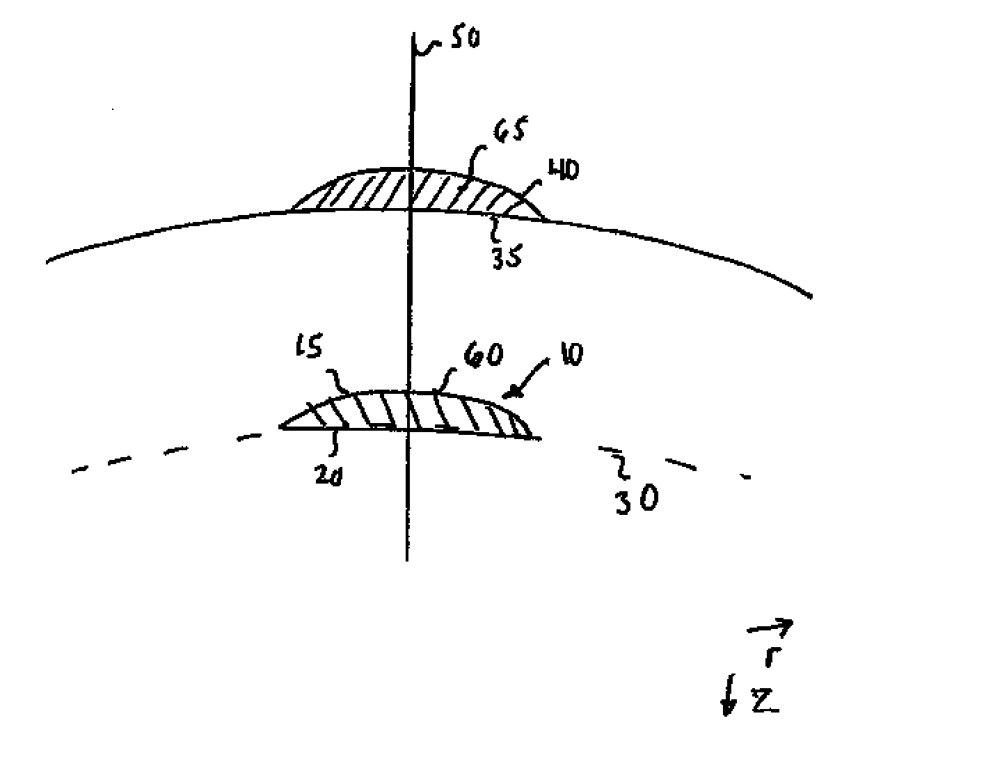
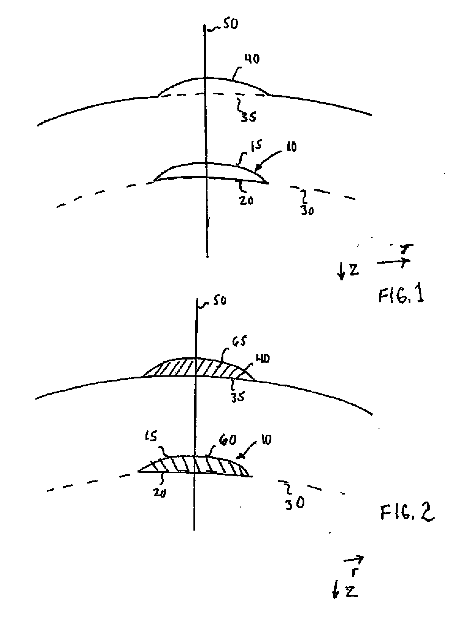
[0013] Described herein are designs and design methods for intracorneal inlays with intrinsic dioper power (i.e., index of refraction different from the surrounding cornea tissue). The designs and design methods achieve a desired refractive change by a combination of the intrinsic diopter power of the inlay and the physical shape of the inlay, which alters the shape of the anterior cornea surface.

[0014]FIG. 1 shows an example of an intracorneal inlay 10 implanted in a cornea. The intracorneal inlay may have a meniscus shape with an anterior surface 15 and a posterior surface 20. The intracorneal inlay 10 may be implanted in the cornea by cutting a flap into the cornea, lifting the flap, placing the inlay on the exposed area of the cornea's interior, and repositioning the flap over the inlay. The flap may be cut using a laser, e.g., a femtosecond lasers a mechanical keratome or manually by a ophthalmic surgeon. The inlay 10 is placed on a flap bed 30 in the cornea. Alternatively, a ...


PUM


Abstract

Described herein are designs and design methods for intracorneal inlays with intrinsic dioper power (i.e., index of refraction different from the surrounding cornea tissue). The designs and design methods achieve a desired refractive change by a combination of the intrinsic diopter power of the inlay and the physical shape of the inlay, which alters the shape of the anterior cornea surface.

Description

FIELD OF THE INVENTION [0001] The field of the invention relates generally to corneal implants, and more particularly, to intracorneal inlays. BACKGROUND INFORMATION [0002] As is well known, abnormalities in the human eye can lead to vision impairment. Some typical abnormalities include variations in the shape of the eye, which can lead to myopia (near-sightedness), hyperopia (far-sightedness) and astigmatism as well as variations in the tissue present throughout the eye, such as a reduction in the elasticity of the lens, which can lead to presbyopia. A variety of technologies have been developed to try and address these abnormalities, including corneal implants. [0003] Corneal implants can correct vision impairment by altering the shape of the cornea. Corneal implants can be classified as an onlay and an inlay. An onlay is an implant that is placed over the cornea such that the outer layer of the cornea, e.g., the epithelium, can grow over and encompass the implant. An inlay is an ...

Claims


Application Information

Patent Timeline
IPC IPC(8): A61F2/14
CPCA61F2/147
Inventor LANG, ALAN
Owner REVISION OPTICS
Learn More