Systems and methods for determining threshold warning distances for collision avoidance

a collision avoidance and threshold technology, applied in the field of collision warning systems, can solve problems such as insufficient, potential collision, and limited methods of conventional warning systems

Inactive Publication Date: 2007-11-01
CATERPILLAR INC
View PDF22 Cites 41 Cited by
  • Summary
  • Abstract
  • Description
  • Claims
  • Application Information

AI Technical Summary

Problems solved by technology

Conventional warning systems may be limited in their methods for determining the appropriate time to provide warning signals.
As a result, objects that enter the machine's stopping distance but are traveling in the same direction at a safe distance from the machine may trigger an alarm, falsely indicating a potential for collision.
Although the collision avoidance system of the '703 patent may provide a warning signal based on the velocity of an object relative to a vehicle, it may not be sufficient.
Additionally, the system of the '703 patent may not accurately determine a threshold condition for providing a warning signal.
For instance, although the system of the '703 patent may provide a warning system if the rate-range ratio (i.e., closure speed) exceeds a predetermined reaction time associated with the operator of the vehicle, it does not, however, differentiate between a direction of travel of a detected object, which could potentially result in erroneous warning signals.
As a result, warning signals associated with objects that are traveling in the same direction as the vehicle may be triggered unnecessarily, while warning signals associated with objects traveling in the opposite direction as the vehicle may not provide adequate operator reaction time.

Method used


Image

  • Systems and methods for determining threshold warning distances for collision avoidance
  • Systems and methods for determining threshold warning distances for collision avoidance
  • Systems and methods for determining threshold warning distances for collision avoidance

Examples


Embodiment Construction

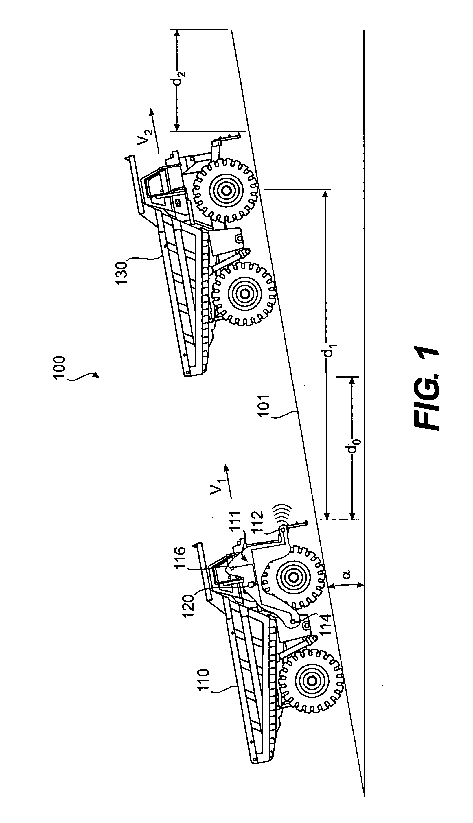
[0015]FIG. 1 illustrates an exemplary environment 100 in which processes and principles consistent with the disclosed embodiments may be implemented. As shown in FIG. 1, environment 100 may include a host machine 110 traveling at a velocity, V1, and a target object 130 traveling at a velocity, V2, wherein the target object is at a distance d0 from host machine 110. Environment 100 may include a traveling surface 101 with a grade a associated with an angle of inclination of traveling surface 101. Although target object 130 is illustrated as a track-type tractor machine it is contemplated that target object 130 may include any mobile or fixed object located within a detectable proximity to host machine 110.

[0016] Machine, as the term is used herein, may include any type of fixed or mobile machine configured to perform a task associated with an industry such as farming, transportation, construction, mining, energy exploration, power generation, etc. and operates between or within envi...


PUM


Abstract

A method for determining a threshold distance for a collision warning system includes receiving, from at least one sensing device, data indicative of a change of position of a target object relative to a host machine. The method further includes receiving data indicative of a velocity of the host machine and determining a closing rate associated with a rate of change of distance between the host machine and the target object based on the data indicative of a change of position of the target object relative to the host machine. The method also includes calculating a velocity of the target object based on the velocity of the host machine and the closing rate. The method further includes determining a threshold distance between the host machine and the target object, wherein the threshold distance is a function of the velocity of the target object, the velocity of the host machine, and a reaction time associated with one or more of the host machine velocity, the target object velocity, or an environmental condition. The method also includes providing a signal indicative of the threshold distance to an alarm system associated with a collision warning system.

Description

TECHNICAL FIELD [0001] This disclosure relates generally to collision warning systems and, more particularly, to systems and methods for adaptively determining threshold warning distances for collision warning systems. BACKGROUND [0002] Collision warning systems are used in a variety of machines, such as aircraft, automotive vehicles, watercraft, etc. These systems often include sensing devices, such as optical sensors, radar systems, etc. that detect the range, position, movement direction, and / or size of objects in proximity to the machine. For example, some conventional collision warning systems calculate a stopping distance associated with the machine based on the velocity of the machine and provide an alarm when an object in proximity to the machine lies within a threshold range. [0003] Conventional warning systems may be limited in their methods for determining the appropriate time to provide warning signals. For example, some of these systems provide an alarm each time an obj...

Claims


Application Information

Patent Timeline
Patent Type & Authority Applications(United States)
IPC IPC(8): G06G7/78G06F17/10
CPCB60W2550/142B60W2550/30G01S2013/9325G01S2013/9353G01S2013/9364G01S13/931G01S2013/9324G01S2013/932B60W2554/80B60W2552/15
Inventor MCDANIEL, MICHAELTRAVIS, DEXTERCOATS, ROBERT
Owner CATERPILLAR INC
Why Eureka
Try Eureka