Light-emitting diode shelf

Inactive Publication Date: 2007-11-08
LED FOLIO CORP
View PDF8 Cites 13 Cited by
  • Summary
  • Abstract
  • Description
  • Claims
  • Application Information

AI Technical Summary

Benefits of technology

[0010]An object of embodiments of the invention is to provide comfortable lighting for a display case.
[0011]Another object of embodiments of the invention is to provid

Problems solved by technology

Point light sources are typically shaded or directed in such way so as not to be directly in the line of sight for an individual since the high intensity of point light sources can cause discomfort.
The entire case is not sufficiently lit by lighting

Method used


Image

  • Light-emitting diode shelf
  • Light-emitting diode shelf
  • Light-emitting diode shelf

Examples


Embodiment Construction

[0024]Reference will now be made in detail to the preferred embodiments of the invention, examples of which are illustrated in the accompanying drawings. The invention may, however, be embodied in many different forms and should not be construed as being limited to the embodiments set forth herein; rather, these embodiments are provided so that this disclosure will be thorough and complete, and will fully convey the concept of the invention to those skilled in the art. In the drawings, the thicknesses of layers and regions are exaggerated for clarity. Like reference numerals in the drawings denote like elements.

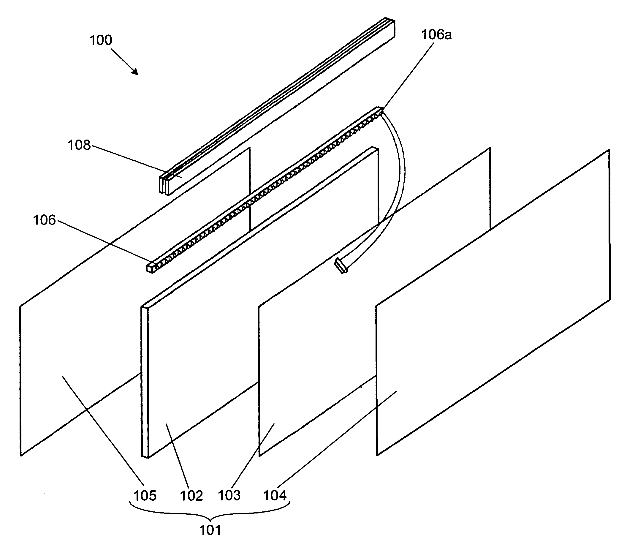
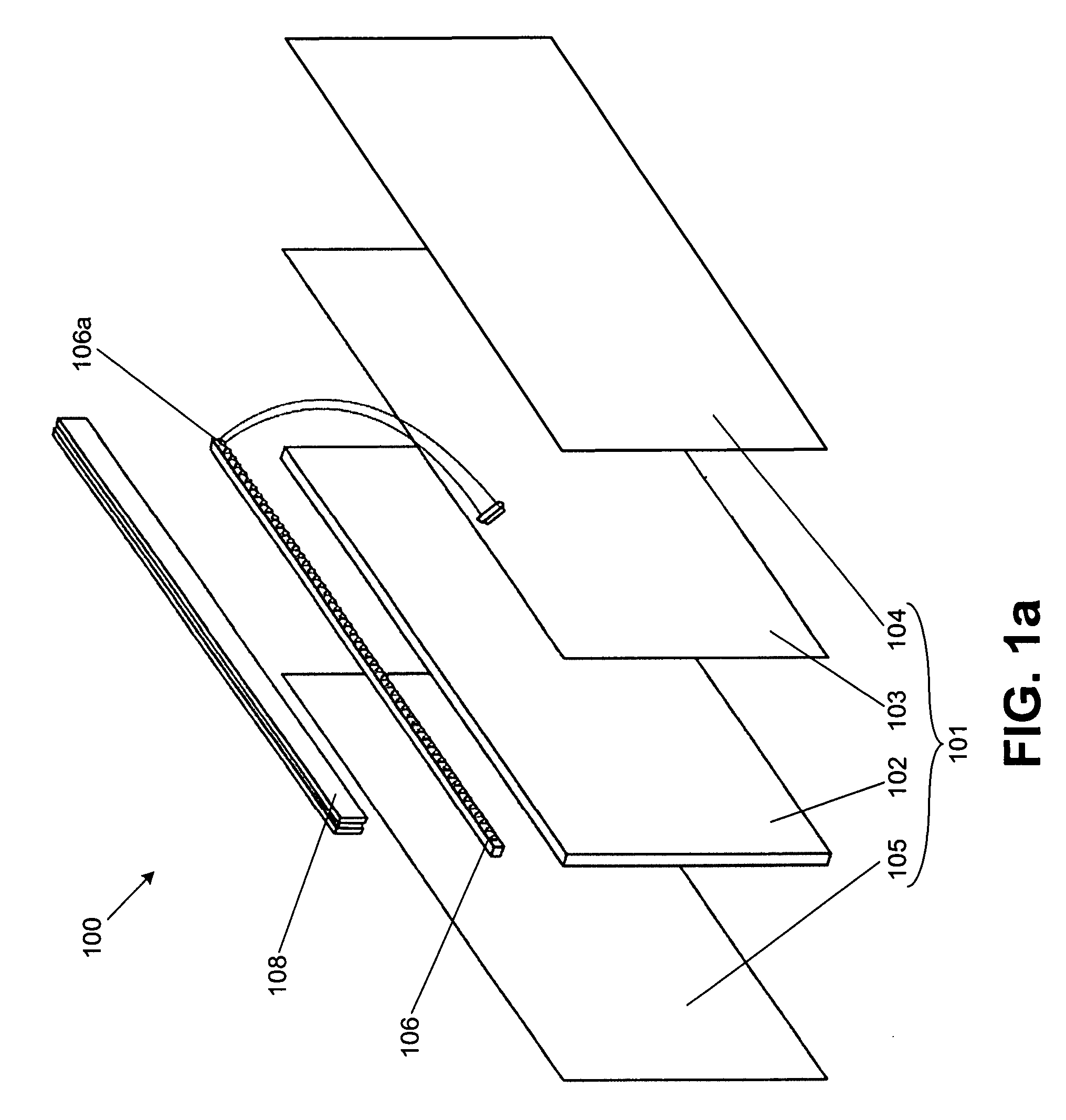
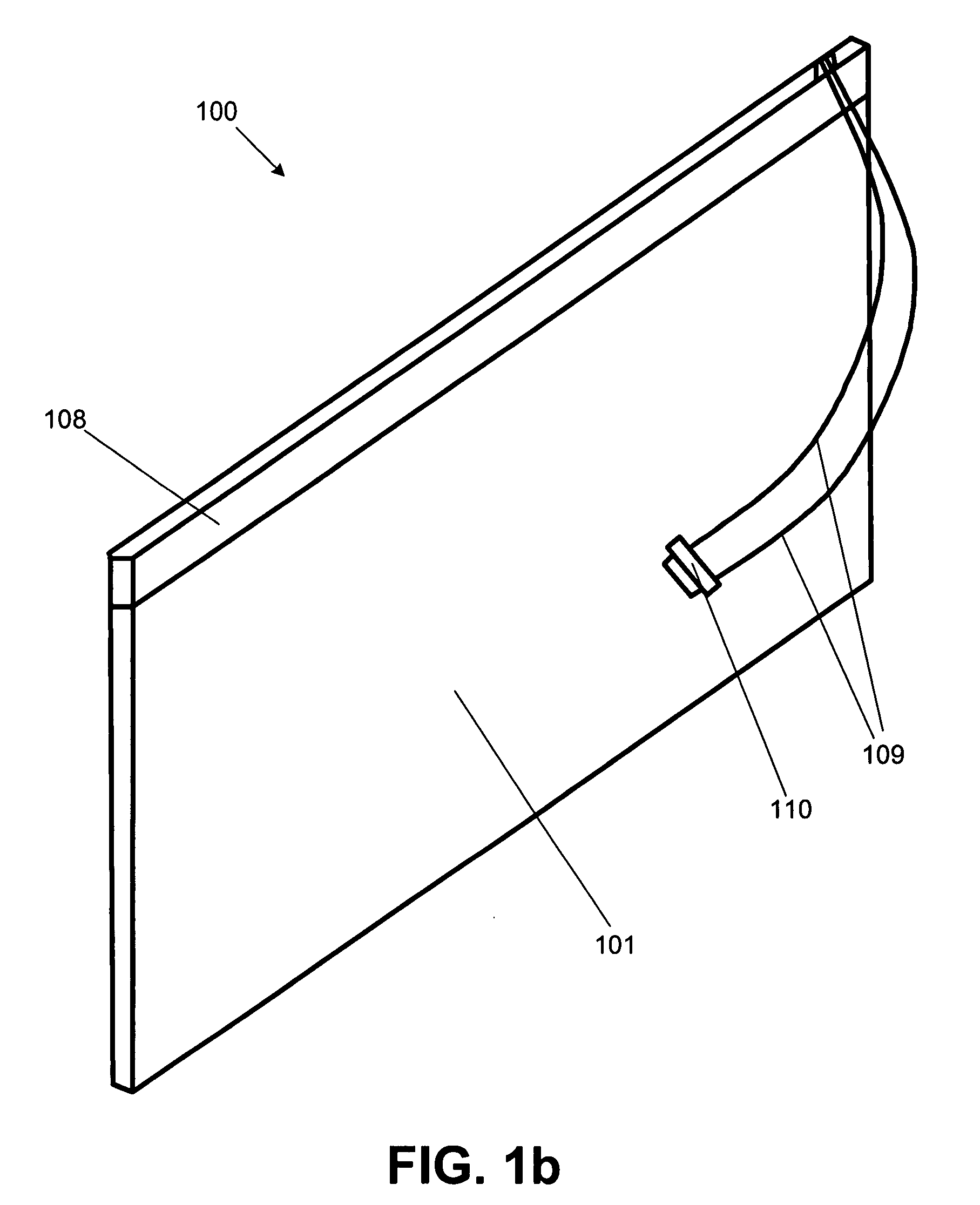
[0025]FIG. 1a is an exploded view of a light-emitting diode shelf according to an embodiment of the invention. FIG. 1b is an assembled view of the light-emitting diode shelf shown in FIG. 1a. As shown in FIGS. 1a and 1b, a light-emitting diode shelf 100 includes a panel assembly 101, a light-emitting diode (LED) strip 106, and a base 108. The panel assembly 101 has a light gu...


PUM


Abstract

A light-emitting diode shelf includes a light guide panel, a reflector covering a first side of the light guide panel, a first diffuser covering a second side of the light guide panel, a second diffuser covering the reflector, a light-emitting diode strip at an edge of the light guide panel, and a base encompassing the light-emitting diode strip and attached to the light guide panel.

Description

[0001]This invention claims the benefit of U.S. Provisional Application No. 60 / 797,676 filed on May 5, 2006, which is hereby incorporated by reference in its entirety.BACKGROUND OF THE INVENTION[0002]1. Field of the Invention[0003]Embodiments of the invention relate to lighting, and more particularly, to a light-emitting diode shelf. Although embodiments of the invention are suitable for a wide scope of applications, it is particularly suitable for the emission of low-intensity planar light from a shelf for display lighting.[0004]2. Discussion of the Related Art[0005]In general, display cases are used to display wares in a commercial setting and prized possessions in a residential settings. Display cases can be open or closed. Closed display cases can have transparent doors on the front of the case, or the front of the case can be transparent and the doors are either at the side or on the back of the case. Some display cases contain shelves on which items can be positioned for displ...

Claims


Application Information

Patent Timeline
IPC IPC(8): G09F13/00
CPCG09F13/18G09F13/04
Inventor KIM, STEVEN
Owner LED FOLIO CORP
Why Eureka
Try Eureka