Front plate for onboard LCD device

Active Publication Date: 2019-02-21
MITSUBISHI GAS CHEM CO INC +1
View PDF0 Cites 0 Cited by
  • Summary
  • Abstract
  • Description
  • Claims
  • Application Information

AI Technical Summary

Benefits of technology

[0019]According to a preferred embodiment, the present invention can provide a front panel that prevents glare, has high abrasion resistance, also has high pencil hardness, and is also

Problems solved by technology

In the case of using such a liquid crystal display for on-board purposes such as car navigation systems, the inside temperature of a car changes greatly from low to high temperatures in an environment so that the front panel is prone to be deformed due to shrinkage and expansion ascribable to thermal fluctuation, leading to problems such as the generation of squeak noise by deformation.
Particularly, in recent years, high retardation dr

Method used


Image

  • Front plate for onboard LCD device
  • Front plate for onboard LCD device
  • Front plate for onboard LCD device

Examples


production example 1

[Production of Resin Composition (B1)]

[0118]A monomer composition consisting of 77.000 mol % of purified methyl methacrylate (manufactured by Mitsubishi Gas Chemical Co., Inc.), 22.998 mol % of purified styrene (manufactured by Wako Pure Chemical Industries, Ltd.) as an aromatic vinyl monomer, and 0.002 mol % of t-amyl peroxy-2-ethylhexanoate (manufactured by ARKEMA Yoshitomi, Ltd, trade name: Luperox 575) as a polymerization initiator was continuously supplied at 1 kg / h to a 10 L complete mixing vessel with a helical ribbon blade where continuous polymerization was performed at a polymerization temperature of 150° C. for an average retention time of 2.5 hours. The polymerization product was continuously discharged from the bottom with the liquid level of the polymerization vessel kept constant, and introduced into a solvent removal apparatus to obtain pellets of a vinyl copolymer resin (B1-1′).

[0119]The obtained vinyl copolymer resin (B1-1′) was dissolved in methyl isobutyrate (man...

production example 2

[Production of Resin Composition (B2)]

[0120]50% by mass of R-200 (manufactured by Denka Corp., weight average molecular weight: 185,000, d1:d2:d3=55:20:25) as a styrene-unsaturated dicarboxylic acid copolymer (D), 50% by mass of methyl methacrylate resin PARAPET HR-L (manufactured by Kuraray Co., Ltd., weight average molecular weight: 90,000) as a resin (C) containing a vinyl monomer, 500 ppm of a phosphorus additive PEP36 (manufactured by Adeka Corp.), and 0.2% of monoglyceride stearate (product name: H-100, manufactured by Riken Vitamin Co., Ltd.) were added. This composition was mixed for 20 minutes using a blender, then melt-kneaded at a cylinder temperature of 240° C. using a twin screw extruder having a screw diameter of 26 mm, and extruded into strands, which were then pelletized in a pelletizer to obtain a resin composition (B2-1). The pellets were able to be stably produced.

production example 3

[Production of Resin Composition (B2)]

[0121]A resin composition (B2-2) was obtained in the same way as in Production Example 2 except that: 60% by mass of R-200 was used as the styrene-unsaturated dicarboxylic acid copolymer (D); and 40% by mass of methyl methacrylate resin PARAPET HR-L was used as the resin (C) containing a vinyl monomer. The pellets were able to be stably produced.


PUM

PropertyMeasurementUnit
Temperatureaaaaaaaaaa
Lengthaaaaaaaaaa
Lengthaaaaaaaaaa

Abstract

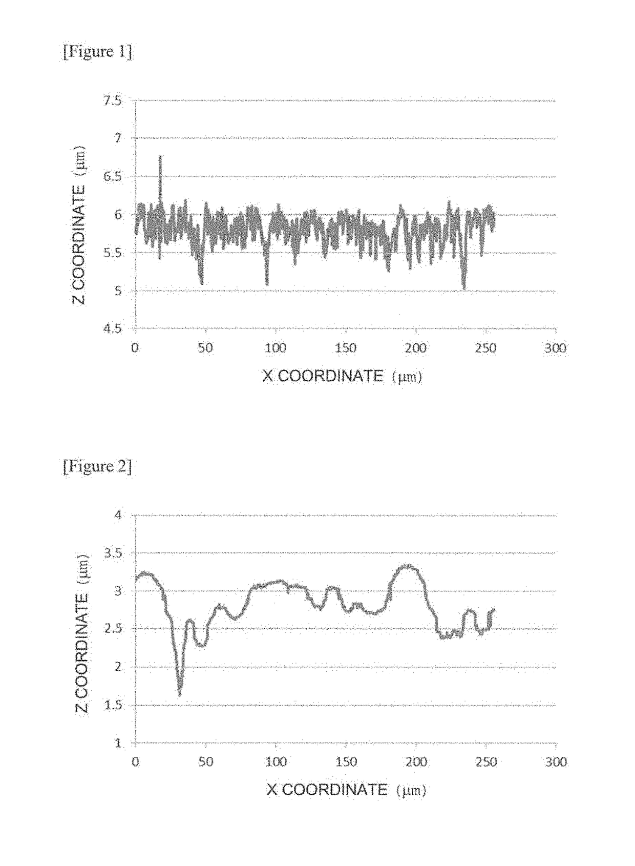
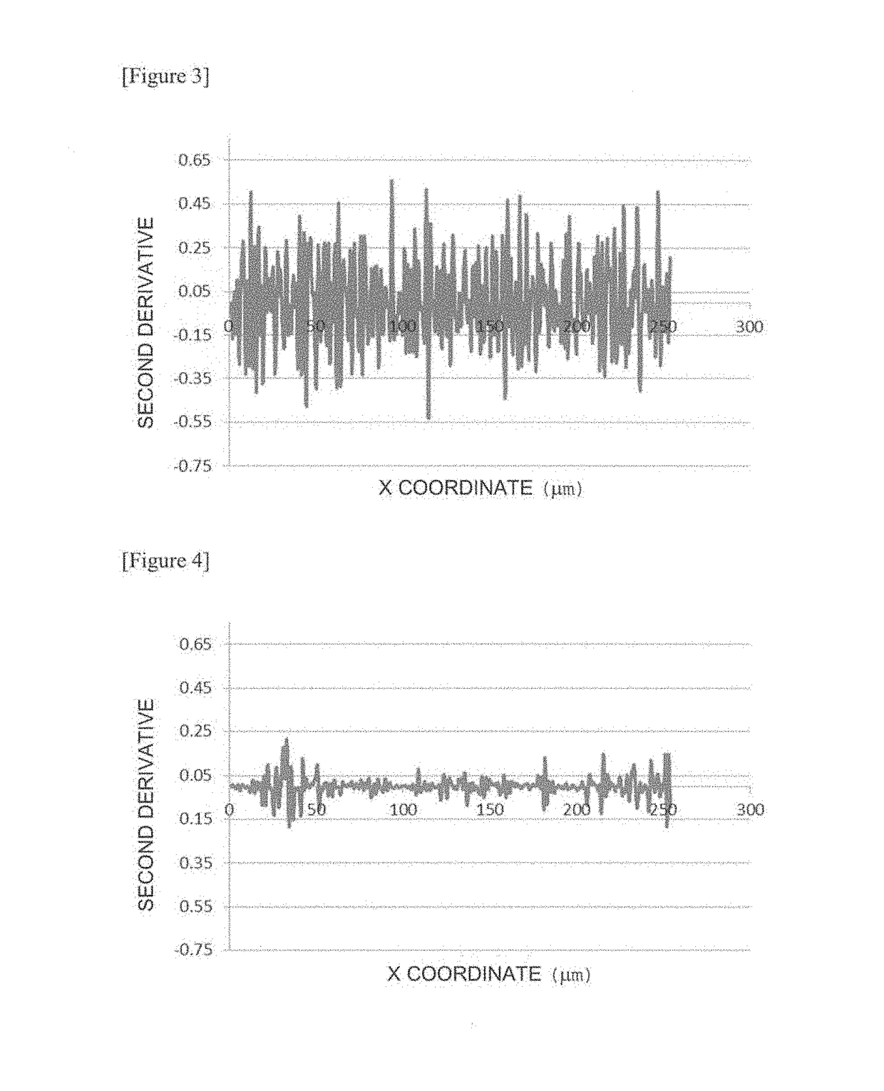
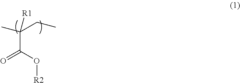
A front panel for on-board liquid crystal displays has a high hardness resin composition (B) on at least one side of a layer containing a resin (A) having a polycarbonate resin (a1). The front panel satisfies the following conditions (i) to (iv): (i) the thickness of the layer containing a high hardness resin composition (B) is 10 to 250 μm, and the total thickness of the layer containing a resin (A) comprising a polycarbonate resin (a1) and the layer containing a high hardness resin composition (B) is 100 to 3,000 μm; (ii) the high hardness resin composition (B) consists of any one of specific resin compositions (B1) to (B3); (iii) the retardation of the front panel is 3,000 nm or more; and (iv) the standard deviation of the second derivative of the irregular shape of the hard coat layer having irregularities is 0.1 or more.

Description

TECHNICAL FIELD[0001]The present invention relates to a front panel for on-board liquid crystal displays. Particularly, the present invention relates to a front panel that prevents glare, has high abrasion resistance, also has high pencil hardness, and is also excellent in the inhibition of warpage, while having excellent impact resistance, heat resistance and anti-glare performance, and is suitable for use in on-board liquid crystal displays.BACKGROUND ART[0002]Front panels are disposed in liquid crystal displays for the purpose of protecting liquid crystal panels, etc. Examples of materials for use in conventional front panels for liquid crystal displays include (meth)acrylic resins typified by polymethyl methacrylate (PMMA).[0003]In recent years, front panels having sheets made of polycarbonate resins have also been used because of having high impact resistance, heat resistance, secondary workability, lightness and transparency, etc. Particularly, a front panel for liquid crystal...

Claims


Application Information

Patent Timeline
IPC IPC(8): B29C47/06B32B27/30B32B27/36C08L25/08C08L33/06C08L69/00G02B1/14G02F1/1335B29C48/18
CPCB32B27/30B32B27/36G02F1/1335B29C48/18C08L69/00G02B1/14C08L25/08C08L33/06B32B27/08B32B27/302B32B27/308B32B27/365B32B2255/10B32B2255/26B32B2307/732B32B2457/202G02F2201/38G02F2201/54G02F1/133331C08L33/12B29C48/022B32B3/30B32B37/15G02F1/13363B29K2069/00B32B2307/536B32B2270/00
Inventor TAKENAKA, HIROKAZUOOSE, YASUOGOTO, TAKUYA
Owner MITSUBISHI GAS CHEM CO INC
Why Eureka
Try Eureka