
Three-dimensional vision reconstruction method for cambered surface reflective workpiece

A reflective workpiece, three-dimensional vision technology, applied in the field of three-dimensional measurement, can solve the problems of easy loss of detail features and decreased measurement accuracy, and achieve the effect of avoiding the loss of detail features, avoiding reflective interference, and improving the accuracy of three-dimensional reconstruction.

Pending Publication Date: 2022-03-22
无锡图创智能科技有限公司
View PDF0 Cites 0 Cited by
  • Summary
  • Abstract
  • Description
  • Claims
  • Application Information

AI Technical Summary

Problems solved by technology

[0006] Aiming at the problem existing in the prior art that when performing three-dimensional measurement on a workpiece with a large arc surface (such as a spherical surface) with high reflective noise, the detail features are easily lost, resulting in a significant drop in measurement accuracy. The present invention provides a curved surface reflective workpiece The 3D visual reconstruction method can reduce the loss of detail features and effectively improve the measurement accuracy

Method used


Image

  • Three-dimensional vision reconstruction method for cambered surface reflective workpiece
  • Three-dimensional vision reconstruction method for cambered surface reflective workpiece
  • Three-dimensional vision reconstruction method for cambered surface reflective workpiece

Examples


Embodiment Construction

[0056] The following disclosure provides many different embodiments or examples for implementing different structures of the present invention. To simplify the disclosure of the present invention, components and arrangements of specific examples are described below. Of course, they are only examples and are not intended to limit the invention. Furthermore, the present disclosure may repeat reference numerals and / or reference letters in different instances, such repetition is for simplicity and clarity and does not in itself indicate a relationship between the various embodiments and / or arrangements discussed. In addition, various specific process and material examples are provided herein, but one of ordinary skill in the art may recognize the use of other processes and / or the use of other materials.

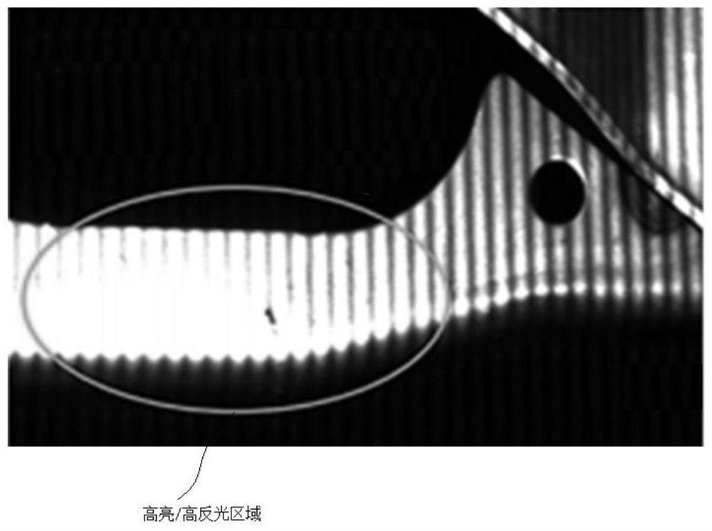
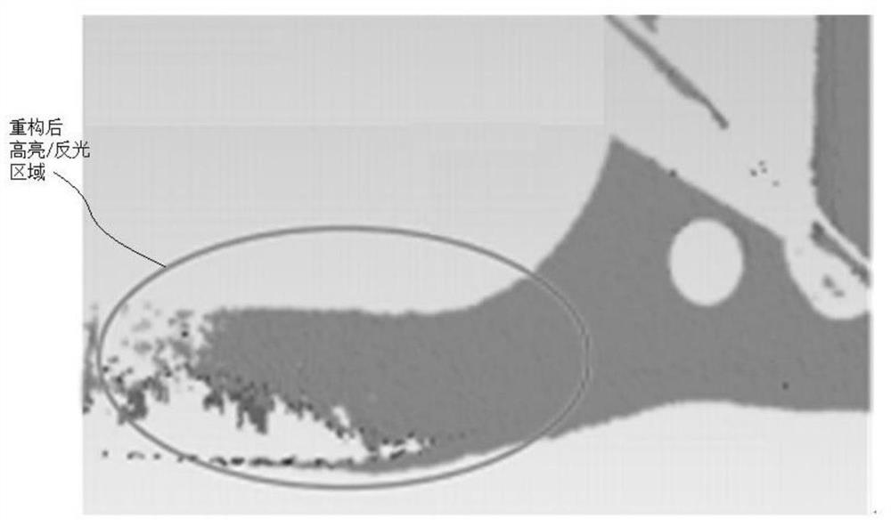
[0057] Figure 1(a) shows a workpiece with a highly reflective surface collected by a 3D camera. It can be seen from the figure that the detailed features of the workpiece are bu...


PUM


Abstract

The invention discloses a three-dimensional visual reconstruction method for a cambered surface reflective workpiece, which is realized based on a 3D camera, and comprises the following steps: setting the exposure time of the 3D camera, projecting light bars to the surface of the workpiece, the light bars being strip-shaped light bars distributed at equal intervals, and collecting original images of the light bars projected on the surface of the workpiece under a low exposure condition; the method comprises the following steps: performing enhancement processing on an original image, obtaining an enhanced image, obtaining an absolute phase diagram of the enhanced image, obtaining a phase gradient diagram of the absolute phase diagram, traversing a pixel value of each point in the phase gradient diagram, if the pixel value of a certain point exceeds a preset value, reducing the pixel value of the point, obtaining a new phase gradient diagram, and according to the new phase gradient diagram, obtaining a new phase gradient diagram; calculating to obtain a new absolute phase diagram, updating the brightness value of each point of the light bar, re-projecting the updated light bar to the surface of the to-be-detected workpiece, performing three-dimensional point cloud reconstruction on the to-be-detected workpiece by using an image decoding and triangulation method, and stopping iteration if the point cloud reconstruction rate is greater than a set threshold value.

Description

technical field [0001] The invention relates to the technical field of three-dimensional measurement, in particular to a method for three-dimensional visual reconstruction of a curved reflective workpiece. Background technique [0002] With the rapid development of modern manufacturing industry, three-dimensional measurement technology is widely used in automatic production, quality control, robot vision, reverse engineering, computer-aided design or manufacturing (CAD / CAM), biomedical engineering and other fields. [0003] At present, in the processing and manufacturing industry, commonly used workpiece measurement methods include: sample measurement method, three-coordinate measurement method and optical measurement method. Sample measurement is mainly used for the quality control of the workpiece processing process, the measurement accuracy is low, the labor intensity is high, and for each type of workpiece, multiple sets of samples need to be manufactured, the cycle is l...

Claims


Application Information

Patent Timeline
IPC IPC(8): G06T17/00G06T7/40G06T7/00G06T5/00
CPCG06T17/00G06T7/0004G06T7/40G06T5/00G06T2207/10028G06T2207/10052G06T2207/30164
Inventor 刘国营葛继
Owner 无锡图创智能科技有限公司
Learn More