Measurement Of Corrosivity

a corrosion monitoring and corrosivity technology, applied in instruments, borehole/well accessories, surveys, etc., can solve the problems of unsatisfactory inhibitor effectiveness, unsatisfactory downhole environment, and inability to measure the corrosivity of the well, so as to achieve greater corrosion protection measures and corrosion rate. the effect of higher ra

Inactive Publication Date: 2007-11-08
CAPCIS
View PDF7 Cites 11 Cited by
  • Summary
  • Abstract
  • Description
  • Claims
  • Application Information

AI Technical Summary

Problems solved by technology

The potential severity of the downhole environments and its detrimental effects, both upon operating and maintenance expenditure, is well documented.
However, as explained in U.S. Pat. No. 5,627,749, the downhole corrosion rate may not be consistent throughout the depth of the wellbore as the environmental conditions such as pressure, temperature, fluid density or velocity, are subject to change.
Therefore, the effectiveness of an inhibitor may not be ideal throughout the entire well profile and the optimization of an inhibitor system cannot be achieved without knowing the corrosion rate relative to the well bore depth.
While this tool is suitable for acquiring corrosion data at a single or a plurality of depths against time, it is not able to provide continuous corrosion data against variable depth.
As a result, it is unable to assist in the identification of depths at which the production tubing etc. is particularly vulnerable to corrosion.
Although these models set out to solve the problems outlined, they have not been fully validated due to the absence of a monitoring device.
Such models cannot be relied on until they can be validated in this way.

Method used


Image

  • Measurement Of Corrosivity
  • Measurement Of Corrosivity
  • Measurement Of Corrosivity

Examples


Embodiment Construction

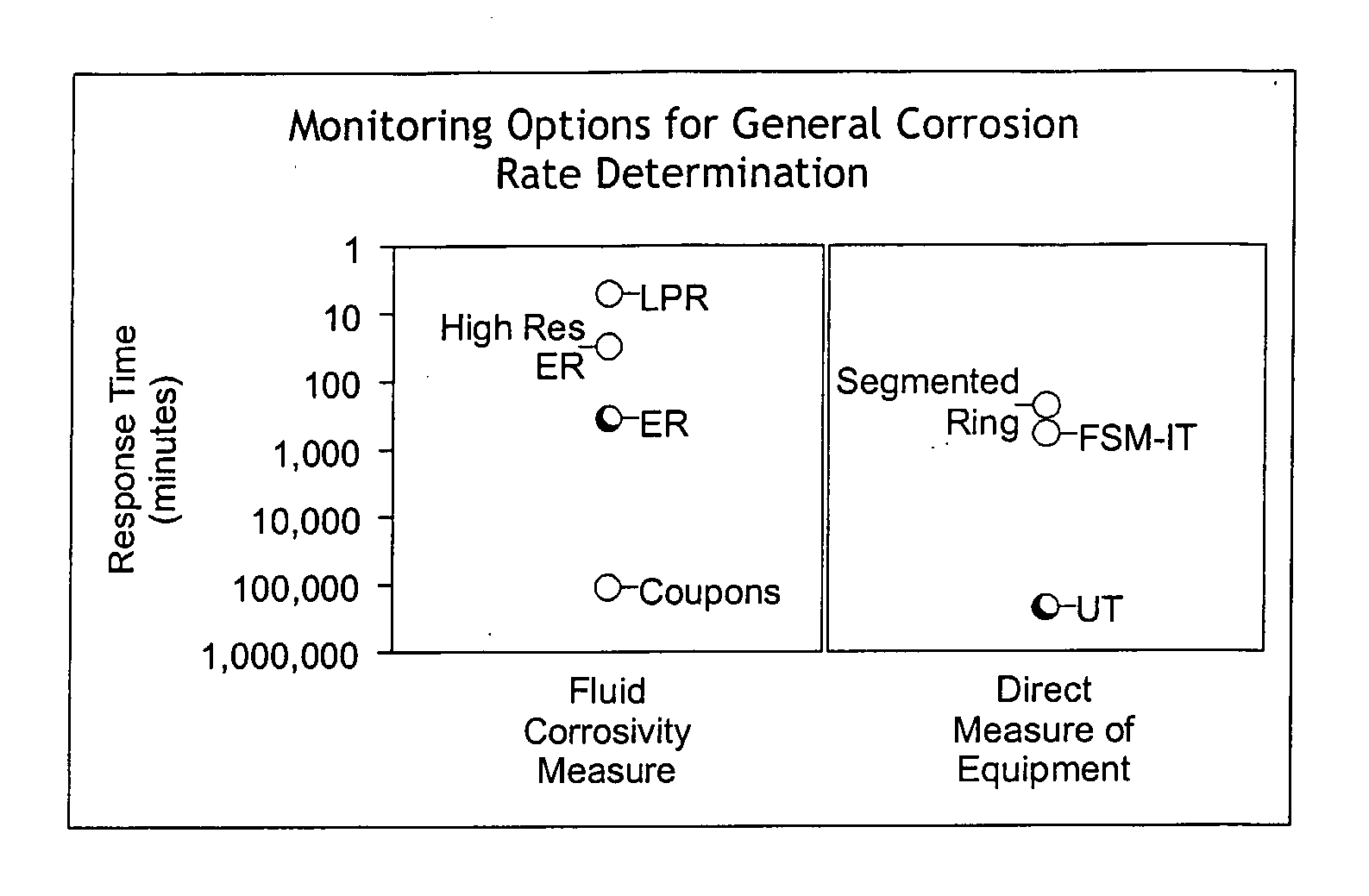
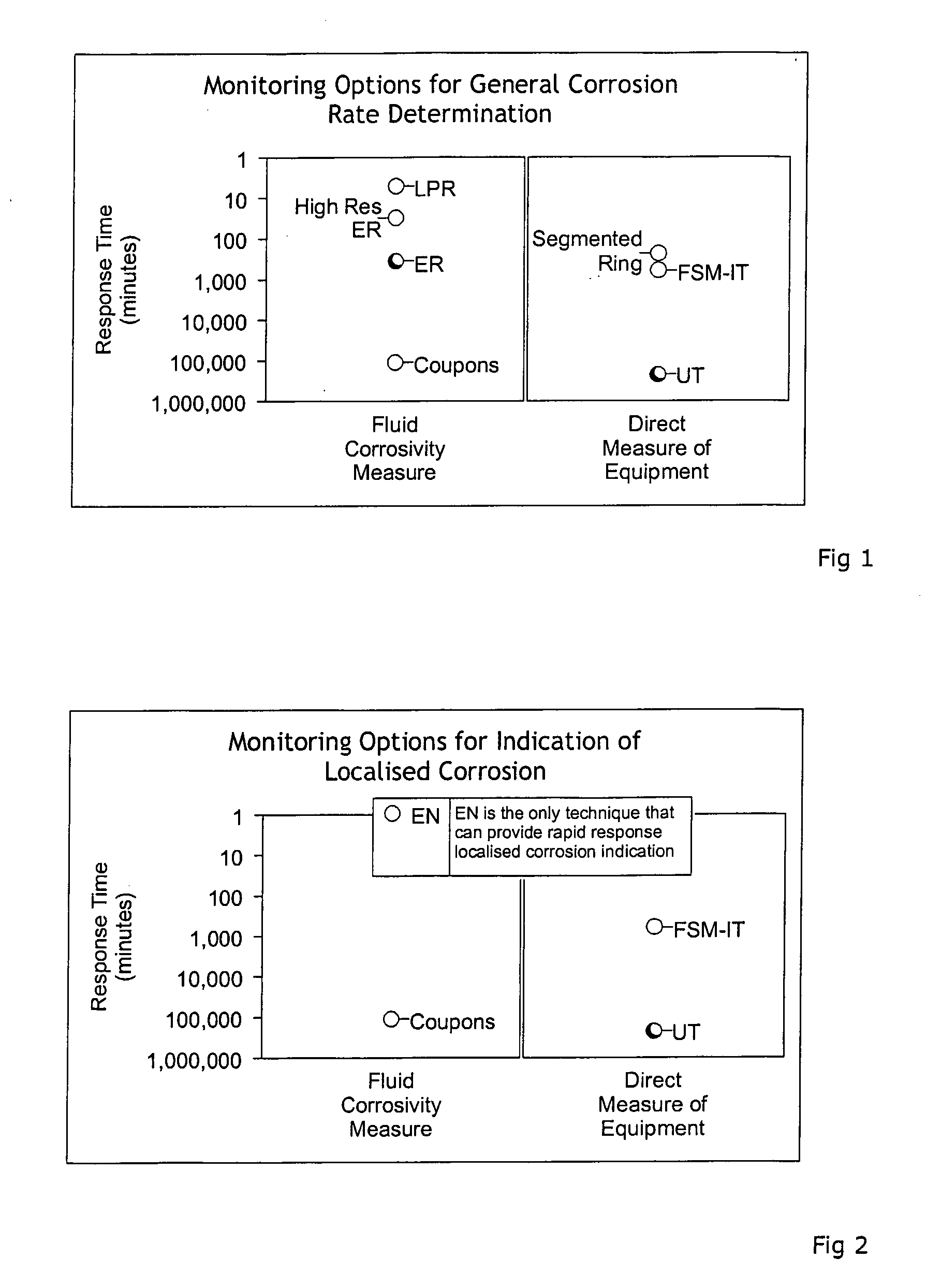
[0019] The present invention aims to overcome the disadvantages associated with current downhole corrosion monitoring techniques and to validate existing corrosion modelling software packages. This is achieved by utilizing a single downhole tool to perform linear polarization resistance (LPR) and electrochemical noise (EN) techniques. These techniques respond to the corrosivity of a fluid much more rapidly, as shown in FIGS. 1 and 2, and enable an operator to deploy the tool via wireline and to obtain real time data.

[0020] As compared to other techniques such as electrical resistance measurement (ER) and weight loss coupons, it can be seen that LPR and EN techniques offer a much shorter response time and are thus suited to development into a realtime monitor capable of reporting the corrosion rates along the length of a wellbore.

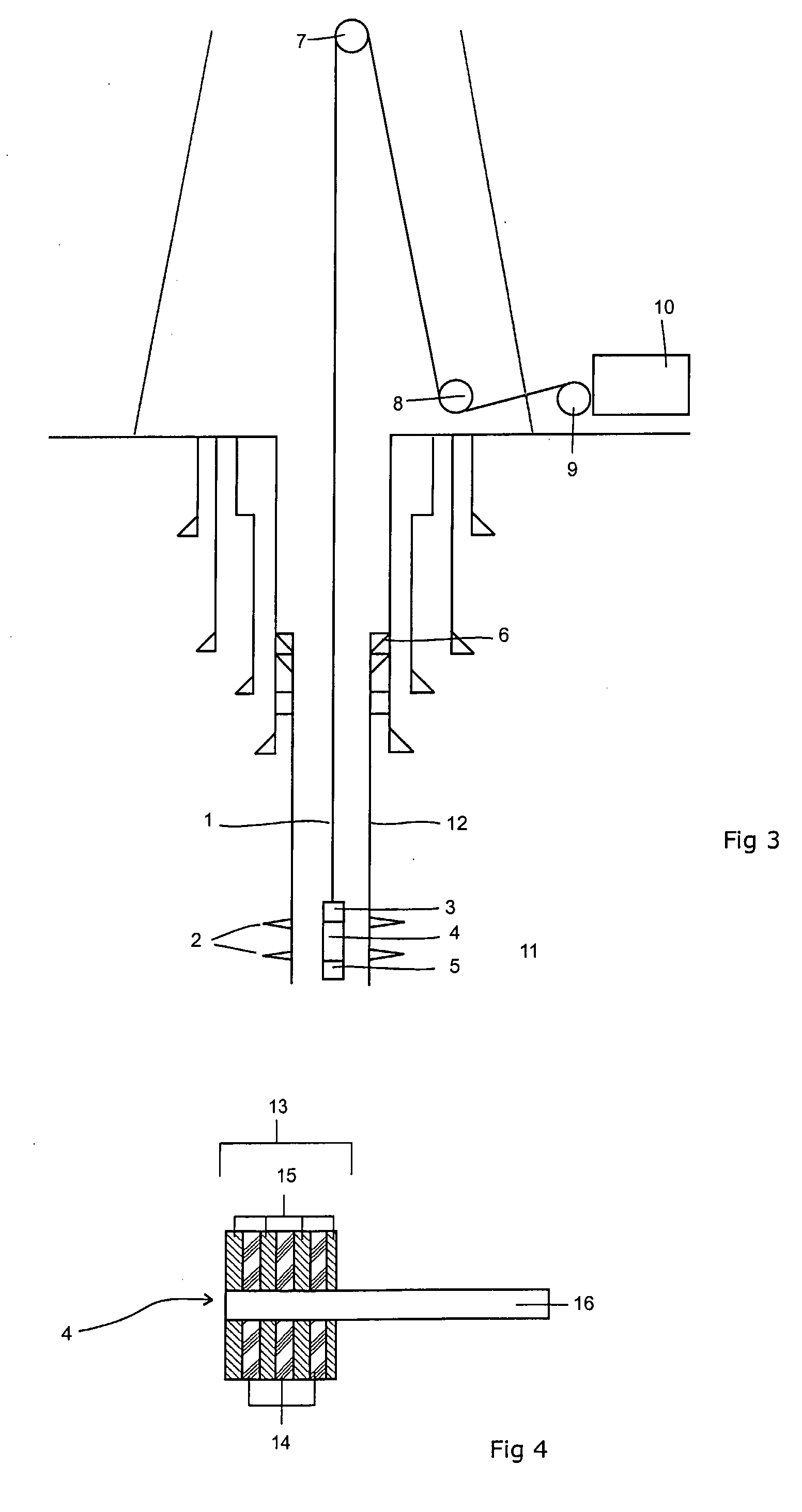
[0021] The tool, while initially moving, aims to passively monitor naturally occurring fluctuations in current and voltage so as not to affect the corrosi...


PUM

PropertyMeasurementUnit
voltagesaaaaaaaaaa
corrosion rateaaaaaaaaaa
temperatureaaaaaaaaaa

Abstract

A downhole corrosion monitor comprises a sensor head suspended on a cable, the cable being extensible so as to raise and / or lower the sensor head downhole and having a signal conductor to return data from the sensor head to the surface, the sensor head comprising a plurality of mutually insulated electrical sensors and means for detecting the voltages and / or currents existing therebetween. The electrical sensors can detect corrosion rate by one or both of linear polarisation rate and electrochemical noise and thus there will usually be at least three. The sensor head can further comprise sensors for at least one of temperature, pressure, vibrations, acceleration, flow sand rate and water cut. A corresponding method of obtaining data is also disclosed, together with a method of designing an item of downhole equipment and the item of downhole equipment thus designed.

Description

FIELD OF THE INVENTION [0001] The invention relates to a downhole corrosion monitoring tool. Preferred embodiments are suitable for deployment into a wellbore by wireline, for the purpose of acquiring corrosion data. The invention also relates to a means of acquiring real time data via wireline. BACKGROUND ART [0002] The potential severity of the downhole environments and its detrimental effects, both upon operating and maintenance expenditure, is well documented. Therefore, techniques which prevent or inhibit the degree of corrosion downhole have long been employed. These techniques have included the replacement of carbon steel drill pipe or production tubing with corrosion resistant alloys (CRAS) and the implementation of chemical inhibitor management programs. However, as explained in U.S. Pat. No. 5,627,749, the downhole corrosion rate may not be consistent throughout the depth of the wellbore as the environmental conditions such as pressure, temperature, fluid density or veloci...

Claims


Application Information

Patent Timeline
Patent Type & Authority Applications(United States)
IPC IPC(8): G01N17/04E21B47/00
CPCE21B47/00G01N17/02E21B47/006
Inventor ATHERTON, ERIC
Owner CAPCIS
Why Eureka
Try Eureka