Adjustable projector mount

a projector and adjustable technology, applied in the field of mounting devices, can solve the problems of difficult positioning, affecting the accuracy of projector positioning, and requiring a considerable amount of time to position, aim and focus the projector, and achieve the effects of high security and theft deterrence, and quick and easy precision projectors

Active Publication Date: 2007-11-08
LEGRAND AV INC
View PDF67 Cites 48 Cited by
  • Summary
  • Abstract
  • Description
  • Claims
  • Application Information

AI Technical Summary

Benefits of technology

[0008] The present invention addresses the need of the industry for a projector mount combining the features of relatively quick and easy precision projector position adjustment in roll, pitch, and yaw, orientations, high security and theft deterrence, and compact size. According to an embodiment of the invention, a mount for attaching a projection device to an overhead structure includes a device interface operably attachable to the projection device and a device orientation adjustment structure operably coupled with the device interface. The device orientation adjustment structure includes at least one upright extending from the device interface and a support structure interface extending from and operably coupled with the at least one upright. The support structure interface h...

Problems solved by technology

Such impromptu arrangements, however, have a number of drawbacks.
First, a considerable amount of time is often needed to position, aim, and focus the projector in advance of the presentation—time that is expended repeatedly whenever a different projector is set up.
Further, it is often difficult to position a portable projector where it is not in the way of persons moving about in the room, or in the line of sight for those viewing the presentation.
Moreover, the wires and cables used to connect the projector with the computer are in the open at ground level, presenting a tripping hazard and an opportunity for damage to the projector if someone comes in contact with them.
These prior ceiling mounting devices have presented certain drawbacks, however.
The channels, however, result in a rather bulky device that may be difficult to harmonize with the aesthetic environment of a presentation room.
In addition, adjustment of the projector for roll, pitch, and yaw may be time consuming and difficult due to the gene...

Method used


Image

  • Adjustable projector mount
  • Adjustable projector mount
  • Adjustable projector mount

Examples


Embodiment Construction

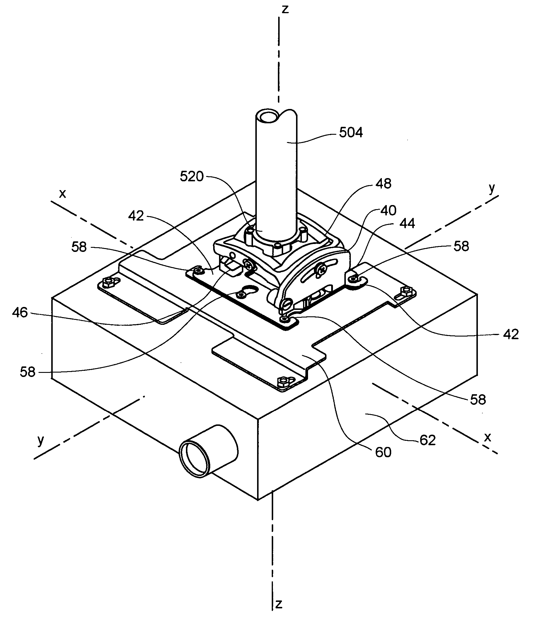
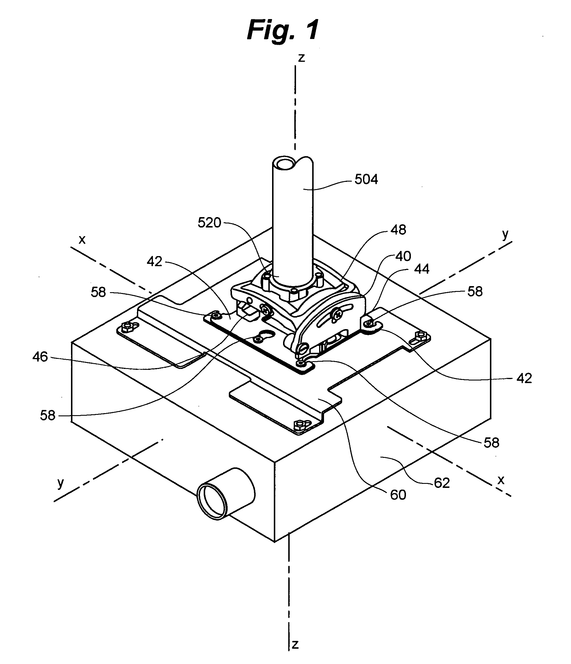
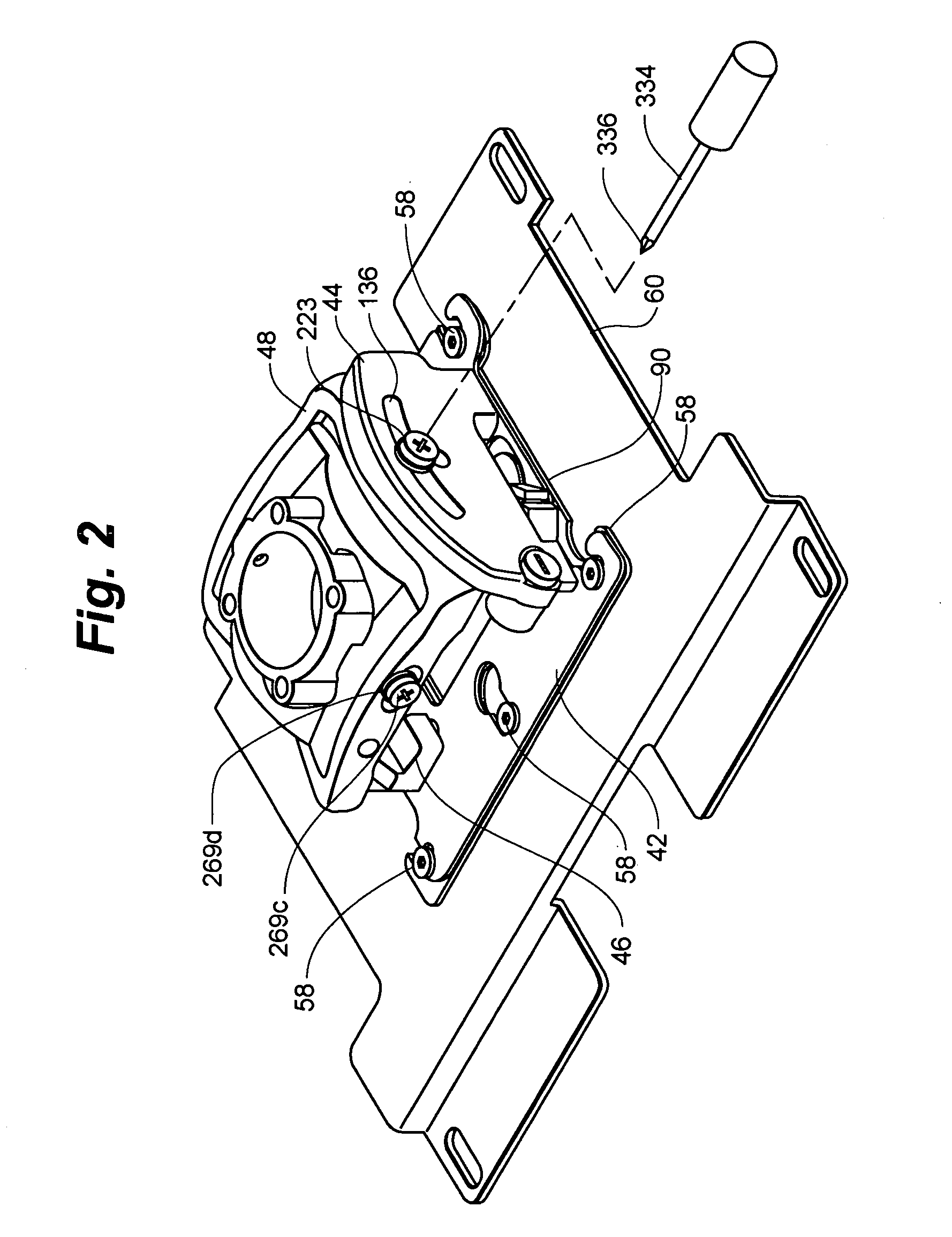
[0095] The accompanying Figures depict embodiments of the mount of the present invention, and features and components thereof. Any references to front and back, right and left, top and bottom, upper and lower, and horizontal and vertical are intended for convenience of description, not to limit the present invention or its components to any one positional or spacial orientation. Any dimensions specified in the attached Figures and this specification may vary with a potential design and the intended use of an embodiment of the invention without departing from the scope of the invention. Moreover, the Figures may designate, for reference purposes, the relative directions of x-y-z coordinate axes as applied to the invention. Any reference herein to movement in an x-axis direction, a y-axis direction, or a z-axis direction, or to rotation about an x-axis, a y-axis or a z-axis, relates to these coordinate axes. The y-axis is oriented fore-and-aft in relation to the mounted device, the z-...


PUM


Abstract

A mount for attaching a projection device to an overhead structure includes a device interface operably attachable to the projection device and a device orientation adjustment structure operably coupled with the device interface. The device orientation adjustment structure has structure defining up to three independent axes for adjustment of projector pitch, roll, and yaw. A single selectively adjustable friction element may be provided to enable projector position to be fixed about for any one or all of the independent axes. A gear adjustment mechanism may be provided to enable fine adjustment of projector position. Moreover, any one or all of the independent axes may pass through the projector device, preferably proximate its center of gravity so that it is self balanced on the mount to ease adjustment.

Description

RELATED APPLICATION [0001] This application is related to U.S. patent application Ser. No. ______, entitled ADJUSTABLE PROJECTOR MOUNT WITH QUICK RELEASE DEVICE INTERFACE, commonly owned by the owners of the present application and filed on even date with this application, said application being fully incorporated herein by reference.FIELD OF THE INVENTION [0002] The present invention relates to mounting devices and more specifically to adjustable mounts for projectors. BACKGROUND OF THE INVENTION [0003] Multi-media presentations performed with video projection equipment have become very common for business and entertainment purposes. Often, the video projection equipment is a portable LCD projector that is placed on a table, cart, or stand in the room, with the image projected on a portion of the wall or a portable screen. Such impromptu arrangements, however, have a number of drawbacks. First, a considerable amount of time is often needed to position, aim, and focus the projector ...

Claims


Application Information

Patent Timeline
IPC IPC(8): F16M5/00
CPCF16M11/04F16M11/041F16M2200/02F16M11/12F16M11/10
Inventor DITTMER, JAYSMITH, PAUL
Owner LEGRAND AV INC
Why Eureka
Try Eureka