Method of charging rechargeable battery and protection circuit for rechargeable battery
a rechargeable battery and protection circuit technology, applied in safety/protection circuits, electric vehicles, transportation and packaging, etc., can solve the problems of increasing the cost of protection circuit boards and the manufacturing cost of rechargeable batteries, and causing ignition or explosion
- Summary
- Abstract
- Description
- Claims
- Application Information
AI Technical Summary
Benefits of technology
Problems solved by technology
Method used
Image
Examples
first embodiment
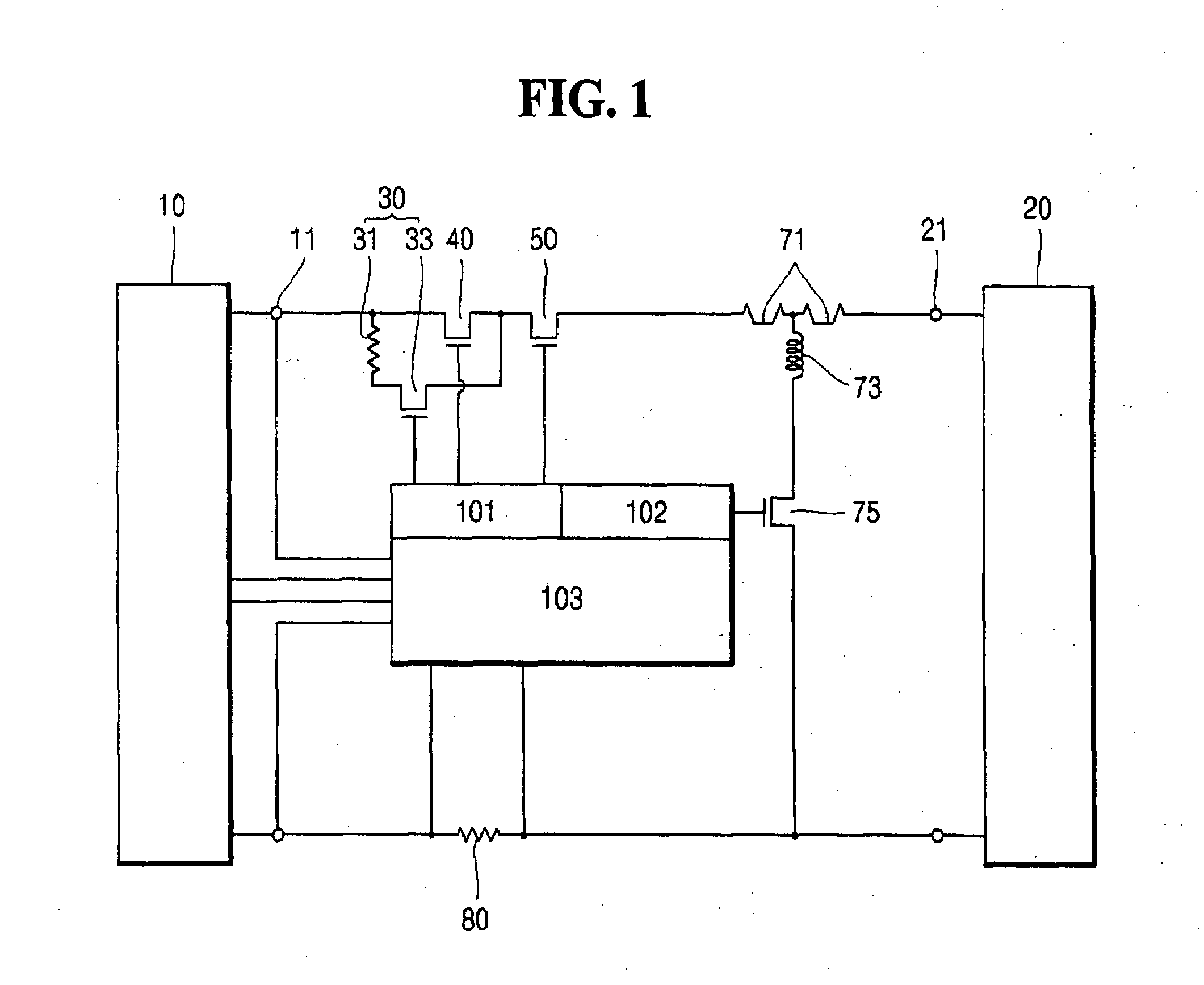
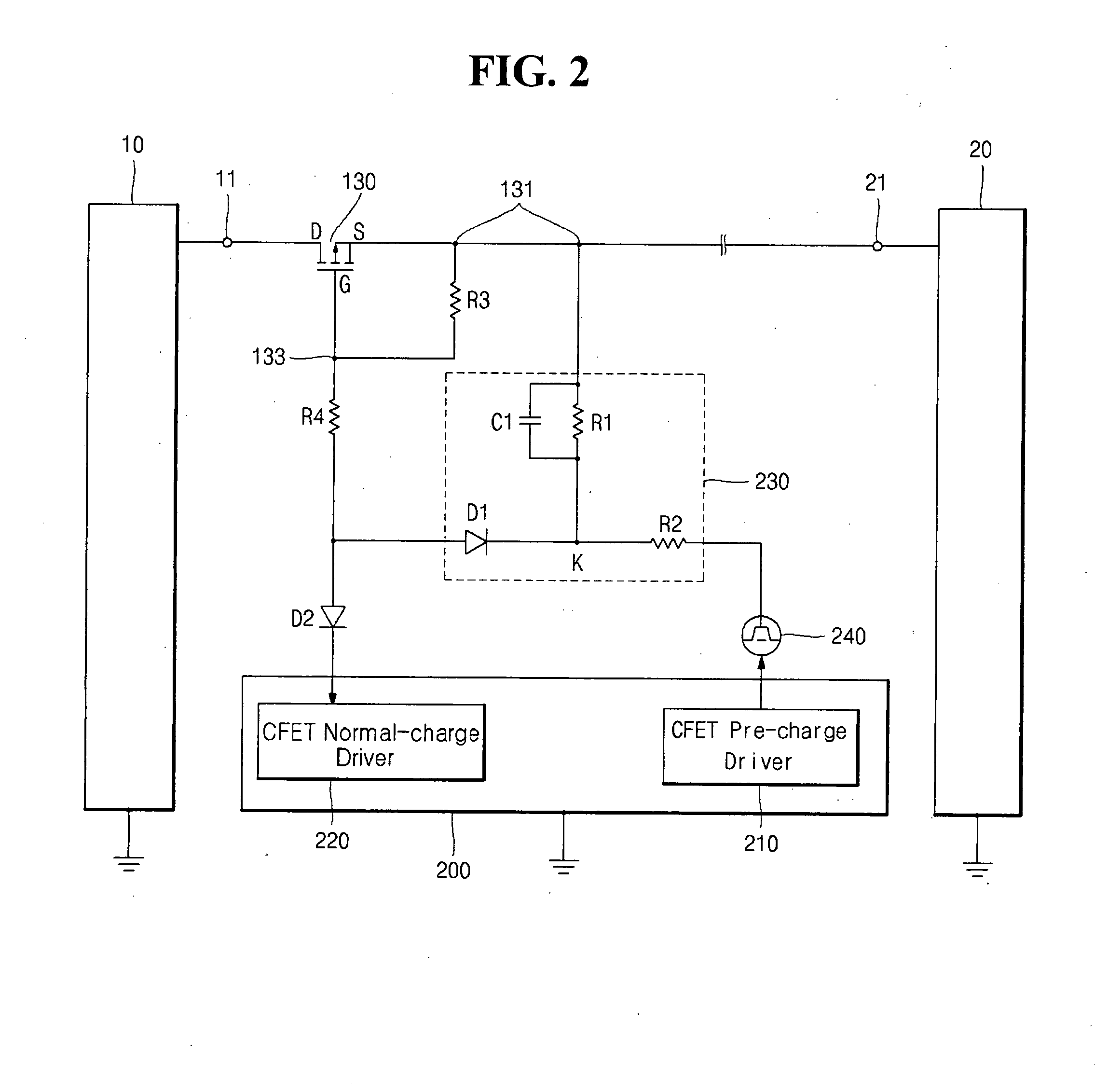
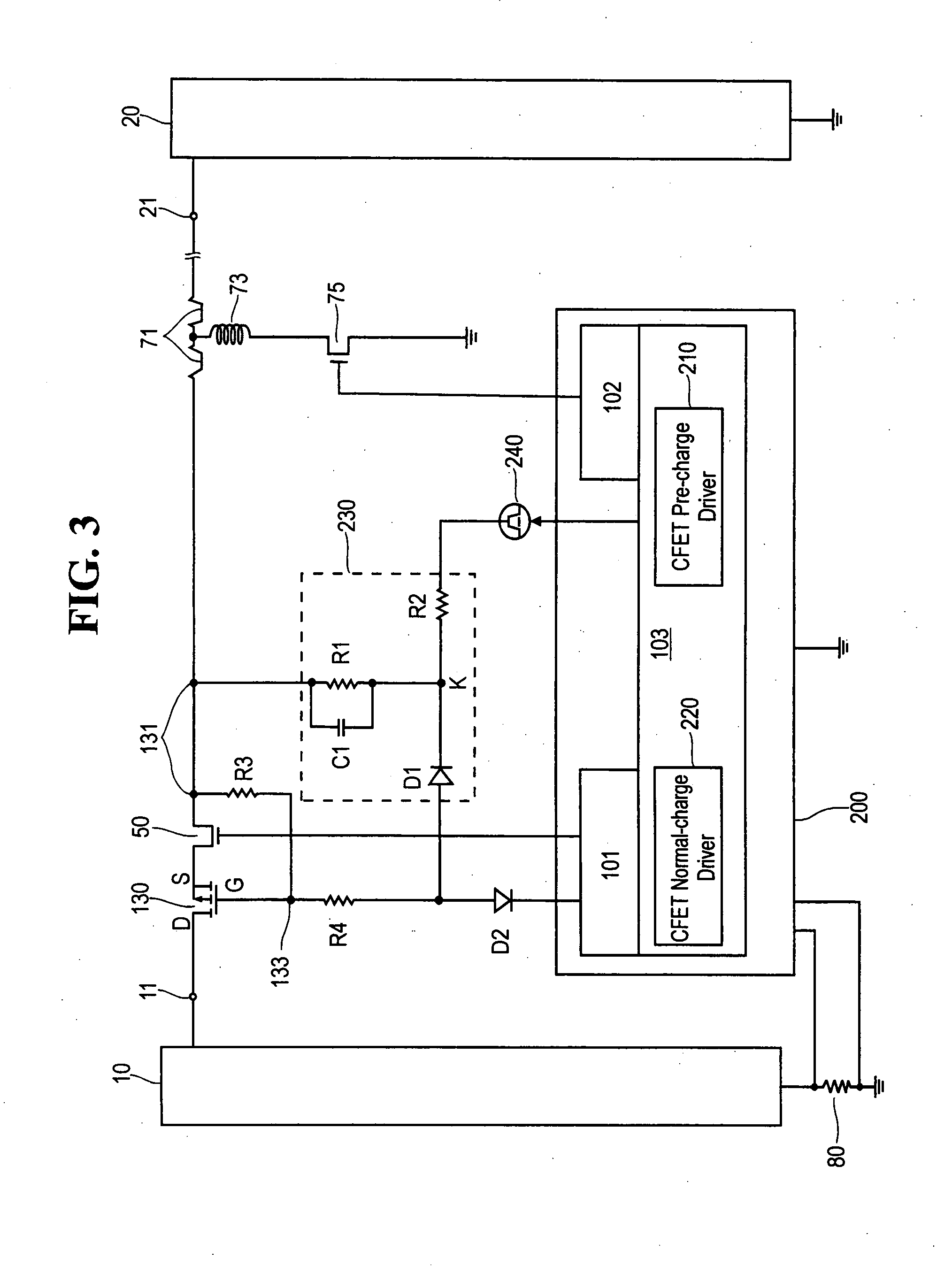
[0057]FIG. 4 illustrates a flow chart of charging process of the rechargeable battery according to the principles of the present invention. The charging process of the rechargeable battery may include a step of detecting charge (S10) and a step of maintaining a low charging rate (S20).
[0058]In the step of detecting charge (S10), protection circuit 200 detects whether the initial charge is obtained or not by sensing the terminal voltage of bare cell 10. The method for sensing the terminal voltage of bare cell 10 may be performed by measuring the terminal voltage of bare cell 10 by a voltage comparator (not shown) built in protection circuit 200. Alternatively, it is possible to detect whether the initial charge is obtained or not by sensing the impedance of bare cell 10.
[0059]In the step of maintaining a low charging rate (S20), protection circuit 200 controls the amount of the current flowing from source electrode S to drain electrode D of charging FET 130 to be at a low level by ad...
second embodiment
[0066]Alternatively, in the present invention, following the step of maintaining a low charging rate (S20), a step of perceiving passage of time (S130) and a step of maintaining a high charging rate (S140) may be performed as illustrated in FIG. 5.
[0067]In the step of perceiving passage of time (S130), protection circuit 200 perceives the passage of a certain time after bare cell 10 is charged by the initial pre-charge charging.
[0068]The step of maintaining a high charging rate (S140) is performed after the step of perceiving passage of time (S130). In the step of maintaining a high charging rate (S140), protection circuit 200 makes the amount of the current flowing through charging FET 130 more than the amount of the current flowing through charging FET 130 in the step of maintaining a low charging rate (S20), by applying relatively high direct voltage, which is higher than the direct voltage in the step of maintaining a low charging rate, to source electrode S of charging FET 130....
third embodiment
[0070]Alternatively, in the present invention, following the step of maintaining a low charging rate (S20), a step of perceiving passage of time (S230) and a step of normal charge (S240) may be performed as illustrated in FIG. 6.
[0071]In the step of perceiving passage of time, protection circuit 200 perceives the passage of the certain time by the program built in protection circuit 200, after bare cell 10 is pre-charged.
[0072]In the step of normal charge, normal-charge driver 220 turns on charging FET 130 by applying a low signal of 0 V or negative voltage to gate electrode G of charging FET 130 by means of the program built-in protection circuit 200. When charging FET 130 is turned on by normal-charge driver 220, the amount of the current adequate for the normal charging flows, and thus the bare cell 10 is normally charged.
[0073]According to the principles of the present invention, it is possible to reduce the manufacturing costs of the rechargeable battery or the rechargeable bat...
PUM
 Abstract
Description
Claims
Application Information
 - R&D
- Intellectual Property
- Life Sciences
- Materials
- Tech Scout
- Unparalleled Data Quality
- Higher Quality Content
- 60% Fewer Hallucinations
Browse by: Latest US Patents, China's latest patents, Technical Efficacy Thesaurus, Application Domain, Technology Topic, Popular Technical Reports.
© 2025 PatSnap. All rights reserved.Legal|Privacy policy|Modern Slavery Act Transparency Statement|Sitemap|About US| Contact US: help@patsnap.com


