
Swaying fitness equipment structure

a technology of fitness equipment and swaying, which is applied in the field of swaying fitness equipment structure, can solve the problems of inability to stabilize the movement of the body, easy deformation, and easy injury of sportsmen and women

Inactive Publication Date: 2007-11-08
ZENG CIAN CHANG
View PDF13 Cites 11 Cited by
  • Summary
  • Abstract
  • Description
  • Claims
  • Application Information

AI Technical Summary

Benefits of technology

"The present invention is a fitness equipment that uses a pivot structure to enable smooth and stable motion. The equipment includes a passive-driven mechanism and a linked mechanism to rotate the wheels. The effector mechanism has multiple swaying bars that act as a pivot structure, which reduces the traveling distance of the drive and allows the effector to withstand larger overloads without deformation. This increases the life span of the equipment overall. The invention can be modified and adapted without changing its main purpose and scope."

Problems solved by technology

Thus, weakness, because of the exercise-induced muscle fatigue, and sports injuries easily occur.
As a result, their structures are easily deformed, and their motions are not stable due to poor design.
Additionally, there is weakness in the effector mechanism because of the long traveling distance of the effector mechanism.
The equipment can be bulky and have a short life span of use.

Method used


Image

  • Swaying fitness equipment structure
  • Swaying fitness equipment structure
  • Swaying fitness equipment structure

Examples


Embodiment Construction

[0017] The features and the advantages of the present invention will be more readily understood upon a thoughtful deliberation of the following detailed description of a preferred embodiment of the present invention with reference to the accompanying drawings.

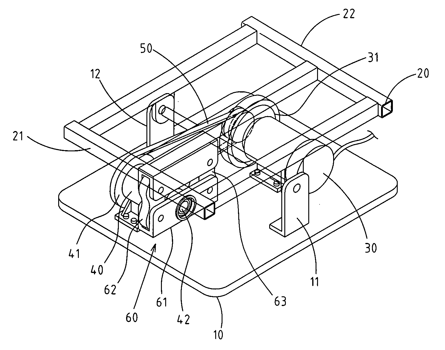
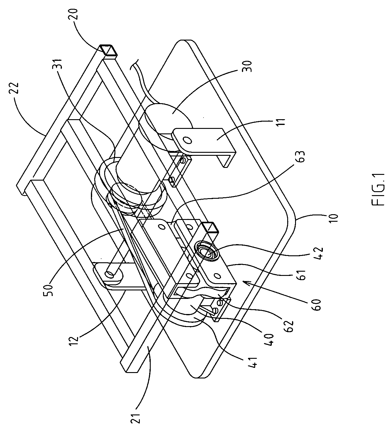
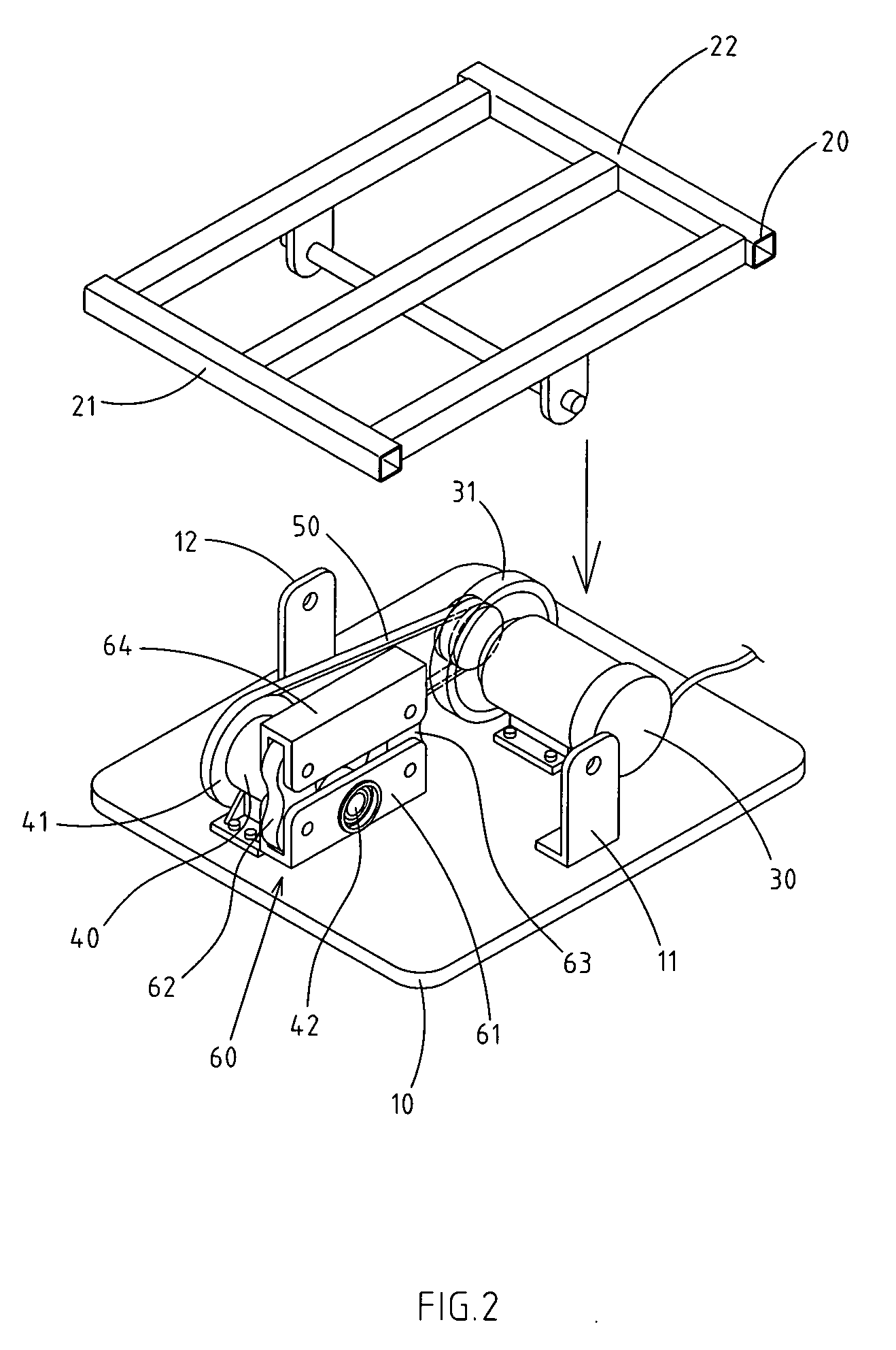
[0018] As shown in FIGS. 1-3, there is a preferred embodiment of a swaying fitness equipment structure.

[0019] A stand is equipped with two brackets 1112 located at the opposite side on its top.

[0020] The invention has an effector 20, wherein two brackets 1112 located at its middle portion constitute a pivot structure. A proper distance between this pivot point and the stand 10 is also maintained for allowing the ability of up and down swaying from side to side due to the function of the pivot constituted by two brackets 1112.

[0021] An active drive mechanism 30 is placed at one side on the top of the stand 10. The mechanism 30 is preferably embodied by a drive motor, and a power output side of said drive mechanism 30 equippe...


PUM


Abstract

The swaying fitness equipment structure includes a stand, which is equipped with two brackets located at the opposite side on its top. There is an effector, having two brackets located at its middle portion forming a pivot structure. A active drive mechanism is located on the top of the stand. A passive-driven mechanism is placed on the top of the stand and faces the active drive mechanism. A linked mechanism is connected between the active drive mechanism and the passive-driven mechanism. The effector mechanism is located at the eccentric axis on the other side of the passive-driven mechanism, causing the effector mechanism to sway.

Description

RELATED U.S. APPLICATIONS [0001] Not applicable. STATEMENT REGARDING FEDERALLY SPONSORED RESEARCH OR DEVELOPMENT [0002] Not applicable. REFERENCE TO MICROFICHE APPENDIX [0003] Not applicable. FIELD OF THE INVENTION [0004] This invention relates in general to a swaying fitness equipment structure, and more particularly to an effector mechanism that consists of a special structure in order to complete the most effective model of swaying operation stabilization and structural enhancement. BACKGROUND OF THE INVENTION [0005] At present, there are various types and functions of sports equipment or bodybuilding equipment in the current market. Most use human hands and feet to propel the equipment in order to accomplish the purpose of fitness. Thus, weakness, because of the exercise-induced muscle fatigue, and sports injuries easily occur. There are various types of active fitness equipment available for the use of exercise and bodybuilding. The principles of operating these machines includ...

Claims


Application Information

Patent Timeline
Patent Type & Authority Applications(United States)
IPC IPC(8): A63B23/08
CPCA61H1/003A61H1/005A61H23/0254A61H2201/0138A61H2201/0149A61H2201/1623A63B23/085A61H2201/164A61H2201/1678A61H2203/0406A61H2203/0431A63B22/16A63B23/08A61H2201/1628
Inventor ZENG, CIAN-CHANG
Owner ZENG CIAN CHANG
Learn More