Methods of manufacturing and assembling electromagnetic assemblies and core segments that form the same

a technology of electromagnetic assemblies and core segments, which is applied in the manufacture of magnetic bodies, magnetic cores, instruments, etc., can solve the problems of large high-tonnage presses, uneconomical production of sizes over 150 mm diameter and achieves high production cost, high production cost, and high production cos

Inactive Publication Date: 2007-11-15
SPANG & CO
View PDF19 Cites 24 Cited by
  • Summary
  • Abstract
  • Description
  • Claims
  • Application Information

AI Technical Summary

Problems solved by technology

Sizes beyond 150 mm diameter are uneconomical to produce, requiring very large high-tonnage presses to consolidate the ceramic or metal powders into the desired shapes.
Commercially available presses capable of more than 1000 tons of compaction force are uncommon and expensive to purchase and operate.
High densities are important in fully developing optimum magnetic properties for any given material, and reductions in pressing pressure lead to inferior core performance.
Pressing areas greater than 6.67 square inches will result in lower pressures and degraded core performance.
More restrictive limitations on maximum core sizes are imposed if more common and economical presses are employed, such as those presses with capacities of only 400 to 750 tons of pressing force.
Circuit designers thus have limits on the size of available cores made from these materials.
These cores are labor intensive to manufacture in large sizes and have other important drawbacks that limit their use.
They can be limited to use at lower frequencies, typically less than 100 kHz, due to high eddy current losses associated with and proportional to the ribbon thickness.
Thinner gages, down to 0.0000125 inches, are commercially available but are extremely expensive, and creating large cores from this delicate material is impractical.
Fabricating long continuous lengths of ribbon at very thin gages that is also wide enough to create the desired final dimensions of the magnetic core is difficult and expensive.
Tape wound cores are also limited to certain metal alloys whose ductility permits fabrication into ribbon form by rolling, or that can be cast to final gauge thickness directly.
Ceramic magnetic materials cannot be formed into ribbons, and, thus, cannot be used in tape-wound configurations.
This approach has limited benefit as the winding cross-section of the core, the area where the coil of wire resides, is not increased by stacking and therefore limits the amount of extra power such a stack can produce.
Higher current densities, however, require heavier gauge wire to prevent overheating and excessive electromagnetic losses, and the hole in the stack of toroids will limit the wire size and number of turns of wire that can be wound.
Therefore, the practice of stacking cores is of limited value when constructing large power inductors.
If the gaps between pieces are too large, the inductance of the assembly is reduced, and if the gap widths are too variable from assembly to assembly, the electrical properties will have excessive variation.
If the gap created by the adhesive (the glue line) varies excessively, the electrical properties of the assembled cores will be unacceptable.
In effect, this creates a large number of very small air gaps between particles after the powder is compressed into a desired shape.
The introduction of yet another source of variation, namely variation in air gaps in the assembled structure, would result in a core that has too broad of a range of inductance values within a production lot, and from lot to lot, and would be non-competitive in the marketplace.
Any process that increases the tolerance on the inductor core is undesirable for one or more reasons: 1) the inductance of a wound core is directly proportional to the square of the number of turns of wire (See, Eq.
2); 2) inductors are usually wound to very specific inductance values; and 3) it is uneconomical to customize the number of turns of wire on a core-by-core basis to adjust for inductance variations resulting from variable air gap dimensions.
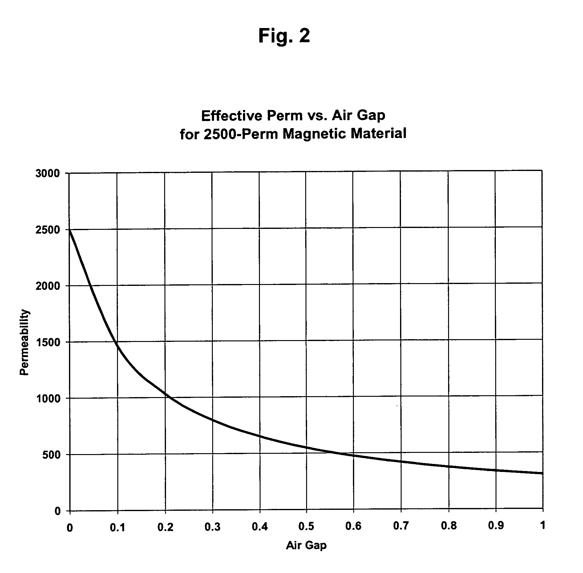
Unfortunately, cores made from high permeability materials suffer the largest drop in inductance with the introduction of air gaps, as shown in FIG. 2.
Therefore the teachings of WO 2005 / 041221 A1 have not found practical application in transformer applications.
However, Japanese Publication No. 04-165607 teach only simple shapes that have no means of establishing registration between segments, and no means to control inductance of the final assembly.
Air gaps created by glue lines that interrupt the magnetic path length are uncontrolled and will lead to an undesirably high degree of variation in inductance from assembly to assembly.

Method used


Image

  • Methods of manufacturing and assembling electromagnetic assemblies and core segments that form the same
  • Methods of manufacturing and assembling electromagnetic assemblies and core segments that form the same
  • Methods of manufacturing and assembling electromagnetic assemblies and core segments that form the same

Examples


example

[0074]FIG. 18 compares a high power inductor design using a segmented core 86 of the invention with a conventional stack of commercially available toroid cores 88. The sample power inductor design compares a soft magnetic core assembled from segments as described herein with that made from a conventional core made from a stack of smaller toroids. The formulas used to calculate the values are well known to those skilled in the art of inductor design and are not shown in the figure. As illustrated in FIG. 18, significant differences in properties, such as the winding area, conductor size, DC copper loss and current density, are shown between the unitary magnetic core assembly of the invention versus the stacked magnetic core in the FIG. 18.

[0075] In the comparison both core assemblies are made from a 26-perm sendust (Fe—Al—Si) alloy. Both cores have essentially identical volumes of magnetic material (136 cm3, 138 cm3) and, therefore, the same energy storage capability when used as an...


PUM

PropertyMeasurementUnit
diameteraaaaaaaaaa
lengthaaaaaaaaaa
lengthaaaaaaaaaa

Abstract

Electromagnetic assemblies, core segments that form the same, and their methods of manufacture. The segments have an interlocking engagement, whereby a variety of assemblies can be produced from a very small number of similar or complementary segments in a manner that provides excellent mechanical stability. The articles and methods of formation offer design flexibility and provide for a large variety of patterns from a small number of primary shapes, provide an economical manufacturing method for large transformer and inductor cores, and improve uniformity of magnetic properties of the assemblies when compared to conventional practices.

Description

CROSS-REFERENCE TO RELATED APPLICATIONS [0001] This patent application is related to the U.S. Patent Application entitled “Electromagnetic Assemblies, Core Segments that Form the Same, and Their Methods of Manufacture” Attorney Docket No. 060206, filed concurrently herewith, the contents of which are incorporated by reference herein in their entirety.FIELD [0002] The invention relates to electromagnetic assemblies, core segments that form the same, and their methods of manufacture. BACKGROUND [0003] Soft magnetic cores made from ceramic materials such as Mn—Zn ferrite, Ni—Zn ferrite, and other soft magnetic ferrite compositions, and from powdered metallic alloys such as Fe, Fe—Al—Si, Fe—Co, Fe—Co—V, Fe—Mn, Fe—P, Fe—Si, Ni—Fe, Ni—Fe—Mo, and other soft magnetic alloys, have been commercially available for decades. More recently, amorphous and nanocrystalline soft magnetic alloys made by a variety of rapid solidification techniques and reduced to powder form by atomization or comminuti...

Claims


Application Information

Patent Timeline
Patent Type & Authority Applications(United States)
IPC IPC(8): H01F41/02H01F7/06G11B5/127
CPCB22F2998/10H01F1/14741H01F1/14766H01F1/344H01F3/14Y10T29/49075H01F41/0206Y10T29/49069B22F3/02B22F3/10
Inventor BOSLEY, LOWELL M.HUTH, JOSEPH F. III
Owner SPANG & CO
Why Eureka
Try Eureka