Eureka AIR delivers breakthrough ideas for toughest innovation challenges, trusted by R&D personnel around the world.

Collision energy absorbing apparatus and railway vehicle equipped with the same

a technology of energy absorption apparatus and equipment, which is applied in the direction of shock absorbers, elastic dampers, bumpers, etc., can solve the problems of reducing affecting the safety of passengers, so as to reduce the load of collision and crush, reduce the load of car body proper, and mitigate the effect of passengers

Inactive Publication Date: 2007-11-15
HITACHI LTD
View PDF14 Cites 31 Cited by
  • Summary
  • Abstract
  • Description
  • Claims
  • Application Information

AI Technical Summary

Benefits of technology

[0020]According to this railway vehicle, the cover that covers the energy absorbing body has a prescribed static strength and, therefore, when a slight impact reaches the energy absorbing body in a condition before the collision energy absorbing apparatus is installed in the car body or during the installation work thereof in the car body, the cover fulfills the role of withstanding the impact. Also, when a slight collision occurs in the railway vehicle, the cover fulfills the role of withstanding a prescribed static load. When a railway vehicle, in whose car body the collision energy absorbing apparatus is installed, collides with an obstacle or the like, before the absorption of the collision energy by the deformation of the energy absorbing body, part of the collision energy is absorbed by being used in the breakage of the cover. Also, by housing the energy absorbing body along with its cover in the limited inner space of the bar body, it is possible to dispose the collision energy absorbing apparatus safely in the interior of the car body and the like.
[0021]In the railway vehicle constructed as described above, a cover is added to the energy absorbing body that constitutes the collision energy absorbing apparatus as a structure having a prescribed static strength. Because the cover itself has static strength, the cover fulfills the role of withstanding a prescribed static load when a slight impact reaches the energy absorbing body or when a slight collision occurs in the car body. Therefore, it is possible to protect the energy absorbing body from a static load due to a slight collision and it is also possible to cope with a breakage of the cover, if it occurs, by replacing the cover alone unless the energy absorbing body is crushed. Also, in the case of an impact which is such that deformation extends to the energy absorbing body, part of the collision energy is used by the breakage of the cover before the deformation of the energy absorbing body. Therefore, the peal load of collision and crush is reduced and it is possible to mitigate loads on the car body proper, passengers and the like.

Problems solved by technology

In a railway vehicle represented by a railroad vehicle, there is a possibility that a collision against an unexpected object occurs during a travel.
However, there is a possibility that the flying object may pierce through the vehicle structure, thereby doing damage to a motorman and a passenger on board.
Even when the underframes collide against each other, the underframes are not crushed because they are robust, with the result that it is impossible to mitigate the impact.
In a railway vehicle, the inner space of the car body is limited and particularly in car end parts in the longitudinal direction of the car body, it is difficult to ensure a sufficient space in which a collision energy absorbing apparatus is to be installed, because equipment, such as a coupling device, is installed there.
Also, in a case where in installing a collision energy absorbing energy apparatus in the car body, a slight impact acts to such an extent that the energy absorbing body itself is partially deformed, it is necessary to replace the whole collision energy absorbing apparatus and a rise in cost is feared.

Method used


Image

  • Collision energy absorbing apparatus and railway vehicle equipped with the same
  • Collision energy absorbing apparatus and railway vehicle equipped with the same
  • Collision energy absorbing apparatus and railway vehicle equipped with the same

Examples


Embodiment Construction

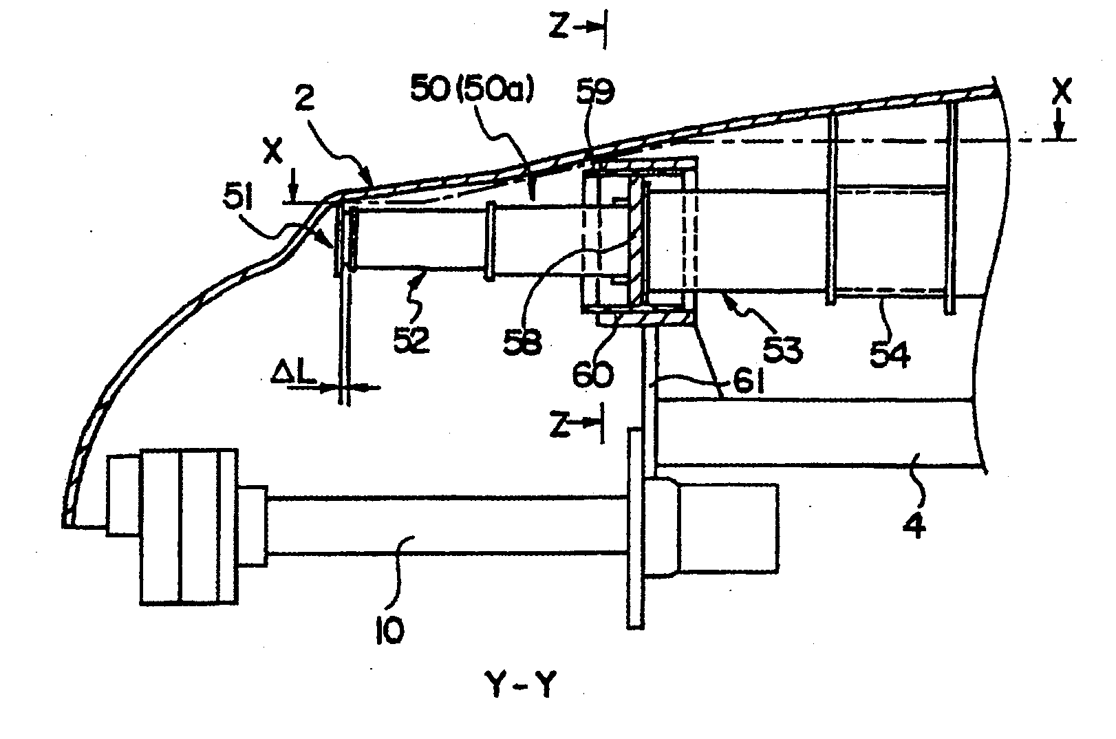
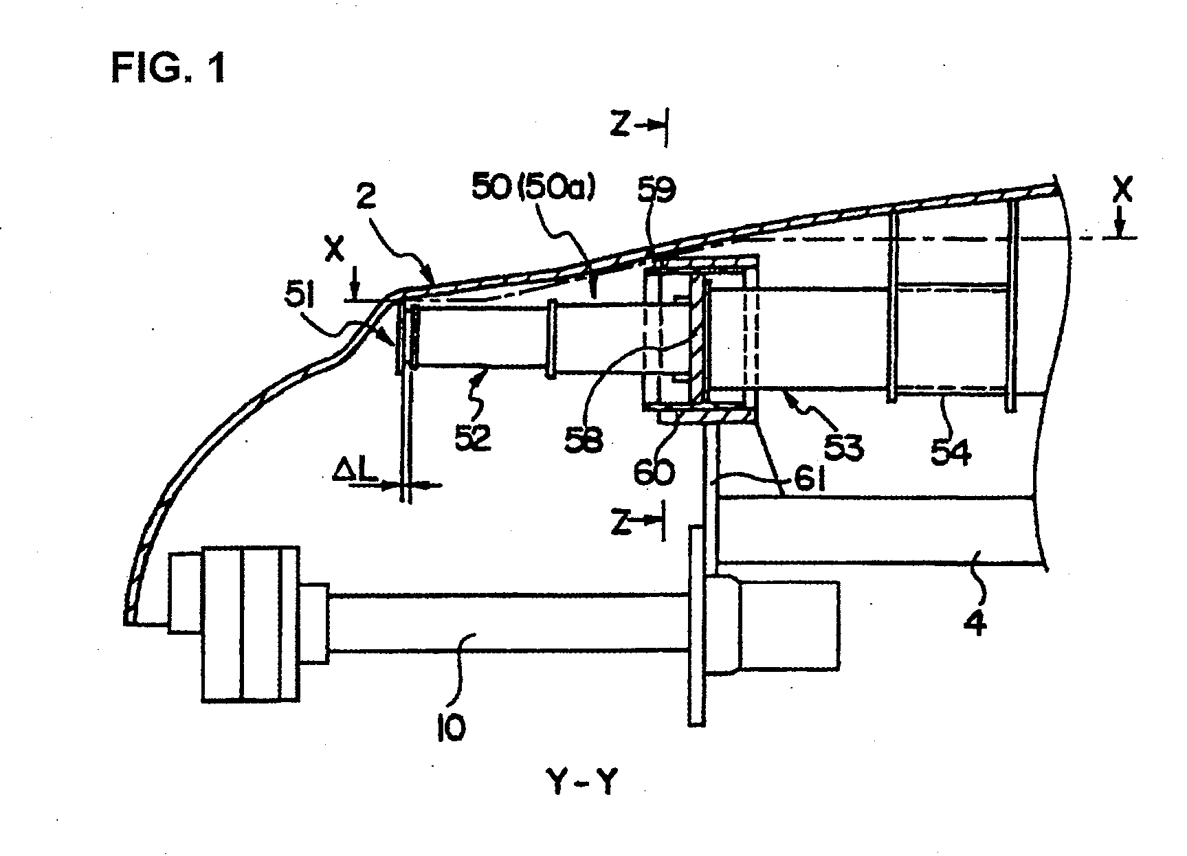
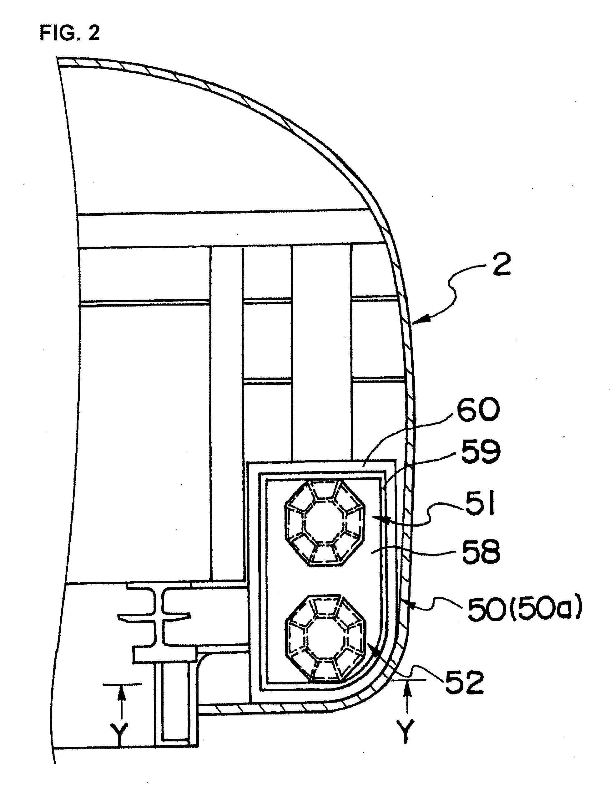
[0033]Next, on the basis of FIGS. 1 to 9, a description will be given of an embodiment which is applied to a car end part, i.e., a forefront part of a forefront vehicle, which is a railway vehicle equipped with a collision energy absorbing apparatus of the present invention. In a forefront vehicle of the embodiment shown in the figure, the profile of a forefront part 2 thereof is formed so as to provide a convex curved surface forward. As shown in FIGS. 1 and 2, a collision energy absorbing apparatus 50 that absorbs part of the collision energy generated upon collision against an obstacle and the like is arranged in the forefront part 2.

[0034]The collision energy absorbing apparatus 50 is installed on each of both sides in the width direction of the forefront vehicle. In FIGS. 1 and 2, only one side in the width direction of the car body is shown. That is, a collision energy absorbing apparatus 50a and a collision energy absorbing apparatus 50b that have the same construction are sy...


PUM


Abstract

Provided is a collision energy absorbing apparatus capable of mitigating loads to the car body proper, passengers and the like by adding a structure combining a prescribed static strength and collision energy absorption performance to an energy absorbing body of the collision energy absorbing apparatus. In a limited inner space of a car body, a cover 80 that covers energy absorbing bodies 51, 52 combines a prescribed static strength and collision energy absorption performance. The cover 80 prevents irregularities, such as the breakage of cylindrical bodies of aluminum alloy, i.e., the energy absorbing bodies 51, 52 in each of the stages of transportation, storage, assembling and the like of the collision energy absorbing apparatus 50. The cover 80 having static strength fulfills the role of withstanding a prescribed static load and in the event of a collision against an obstacle, the cover 80 is broken earliest and reduces a peak load of crush, with the result that part of the collision energy is used in the breakage of the cover 80. As a result of this, the cover 80 can contribute to the absorption and mitigation of the collision energy.

Description

[0001]The present application is based on and claims priorities of Japanese patent application No. 2006-131981 filed on May 10, 2006 and Japanese patent application No. 2007-064585 filed on Mar. 14, 2007, the entire contents of which are hereby incorporated by reference.BACKGROUND OF THE INVENTION[0002]1. Field of the Invention[0003]The present invention relates to a collision energy absorbing apparatus that is applied particularly to a railway vehicle, such as a railroad vehicle and a monorailway vehicle, to mitigate an impact during a collision against an obstacle or the like and a railway vehicle equipped with the apparatus.[0004]2. Description of the Related Art[0005]In a railway vehicle represented by a railroad vehicle, there is a possibility that a collision against an unexpected object occurs during a travel. In the case of a railroad vehicle, examples of an unexpected object in past collision accidents include various kinds ranging from large objects, such as a road vehicle...

Claims


Application Information

Patent Timeline
IPC IPC(8): B61D15/06F16F7/12
CPCB61D15/06B61K13/00B61G11/00
Inventor MOCHIDA, TOSHIHIKOYAMAGUCHI, TAKASHINAKAMURA, HIDEYUKI
Owner HITACHI LTD
Why Eureka
Eureka Blog
Learn More