
Mud pump systems for drilling operations

a pump system and drilling operation technology, applied in the direction of machines/engines, positive displacement liquid engines, borehole/well accessories, etc., can solve the problems of a relatively large footprint of certain prior “triplex” systems, a relatively complex and relatively heavy drive system, etc., and achieve the effect of increasing efficiency

Inactive Publication Date: 2007-11-15
VARCO I P INC
View PDF35 Cites 15 Cited by
  • Summary
  • Abstract
  • Description
  • Claims
  • Application Information

AI Technical Summary

Benefits of technology

The present invention is about a system for pumping drilling fluid used in wellbore operations. The system uses a permanent magnet linear motor to operate a pump to pump the fluid. The use of a linear motor allows for increased efficiency.

Problems solved by technology

The patent text discusses drilling systems and mud pumps used in drilling operations. The technical problem addressed in the text is the complexity and heavy weight of certain mud pumps and mud pump systems, which require constant lubrication and have a large footprint.

Method used


Image

  • Mud pump systems for drilling operations
  • Mud pump systems for drilling operations
  • Mud pump systems for drilling operations

Examples


Embodiment Construction

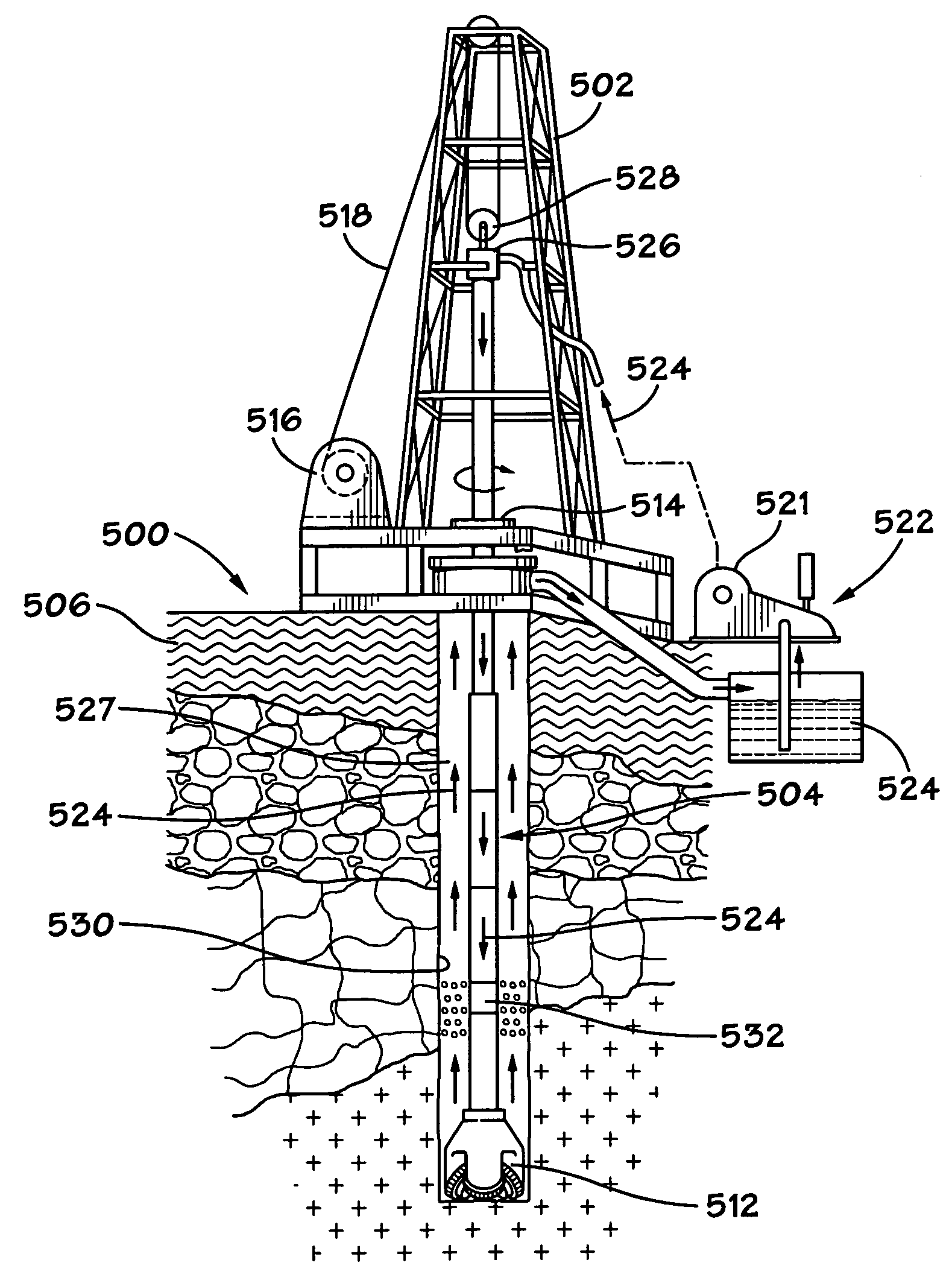
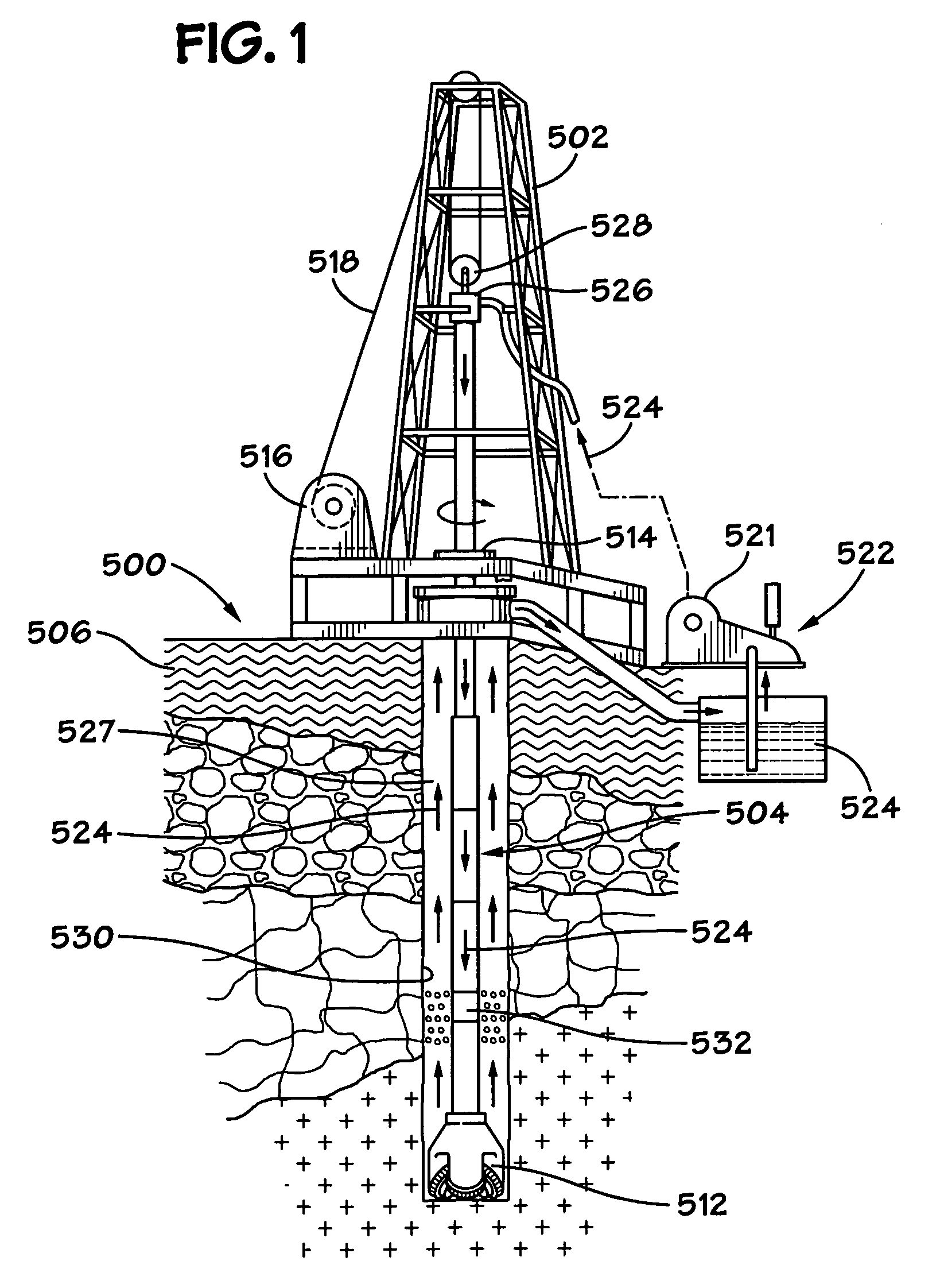
[0033] The system 500 shown in FIG. 1 includes a derrick 502 from which extends a drillstring 504 into the earth 506. The drillstring 504, as is well known, can include drill pipes and drill collars. A drill bit 512 is at the end of the drillstring. A rotary system 514, top drive system 526, and / or a downhole motor 532 (“fluid motor”, “mud motor”) may be used to rotate the drillstring 504 and the drill bit 512. A typical drawworks 516 has a cable or rope apparatus 518 for supporting items in the derrick 502. A mud pump system 522 with one, two, three-to-ten, or more mud pumps 521 according to the present invention supplies drilling fluid 524 to the drillstring 504. Drilling forms a wellbore 530 extending down into the earth 506.

[0034] During drilling, the drilling fluid 524 is pumped by pump(s) 521 of the mud pump system 522 into the drillstring 504 (thereby operating a downhole motor 532 if such an optional motor is used). Drilling fluid 524 flows to the drill bit 512, and then fl...


PUM


Abstract

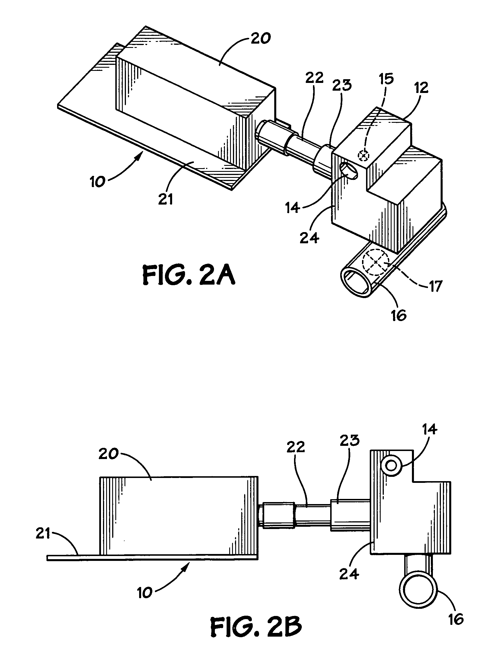
A system for pumping fluid (e.g., but not limited to, drilling fluid), the system having pump apparatus with a pumping section and a motor section, the pumping section having an inlet and an outlet, the motor section having a shaft for reciprocating in and out of the pumping section to alternately suck fluid into the inlet and pump fluid out the outlet, and the motor being a permanent magnet linear motor for moving the shaft in a reciprocating motion, e.g., but not limited to, vertically or horizontally; and methods for using such a system.

Description


Claims


Application Information

Patent Timeline
Owner VARCO I P INC
Learn More