Positioning Apparatus and Positioning System Having the Same

a positioning system and positioning apparatus technology, applied in the direction of positioning apparatus, metal-working machine components, manufacturing tools, etc., can solve the problems of high manufacturing cost, troublesome manufacturing and attaching of taper bush and female taper hole, etc., and achieve the effect of simple and compact positioning system

Inactive Publication Date: 2007-11-15
KOSMEK LTD (JP)
View PDF9 Cites 6 Cited by
  • Summary
  • Abstract
  • Description
  • Claims
  • Application Information

AI Technical Summary

Benefits of technology

[0021] By the construction described above, a simp

Problems solved by technology

According to the above-described prior art, it can be expected that the work pallet is accurately and firmly fixed to the reference member, however, the prior art has the following problem.
The taper bush must be attached to the work pal

Method used


Image

  • Positioning Apparatus and Positioning System Having the Same
  • Positioning Apparatus and Positioning System Having the Same
  • Positioning Apparatus and Positioning System Having the Same

Examples


Embodiment Construction

[0027] Hereinafter, an embodiment of the present invention will be described with reference to FIG. 1A through FIG. 2B.

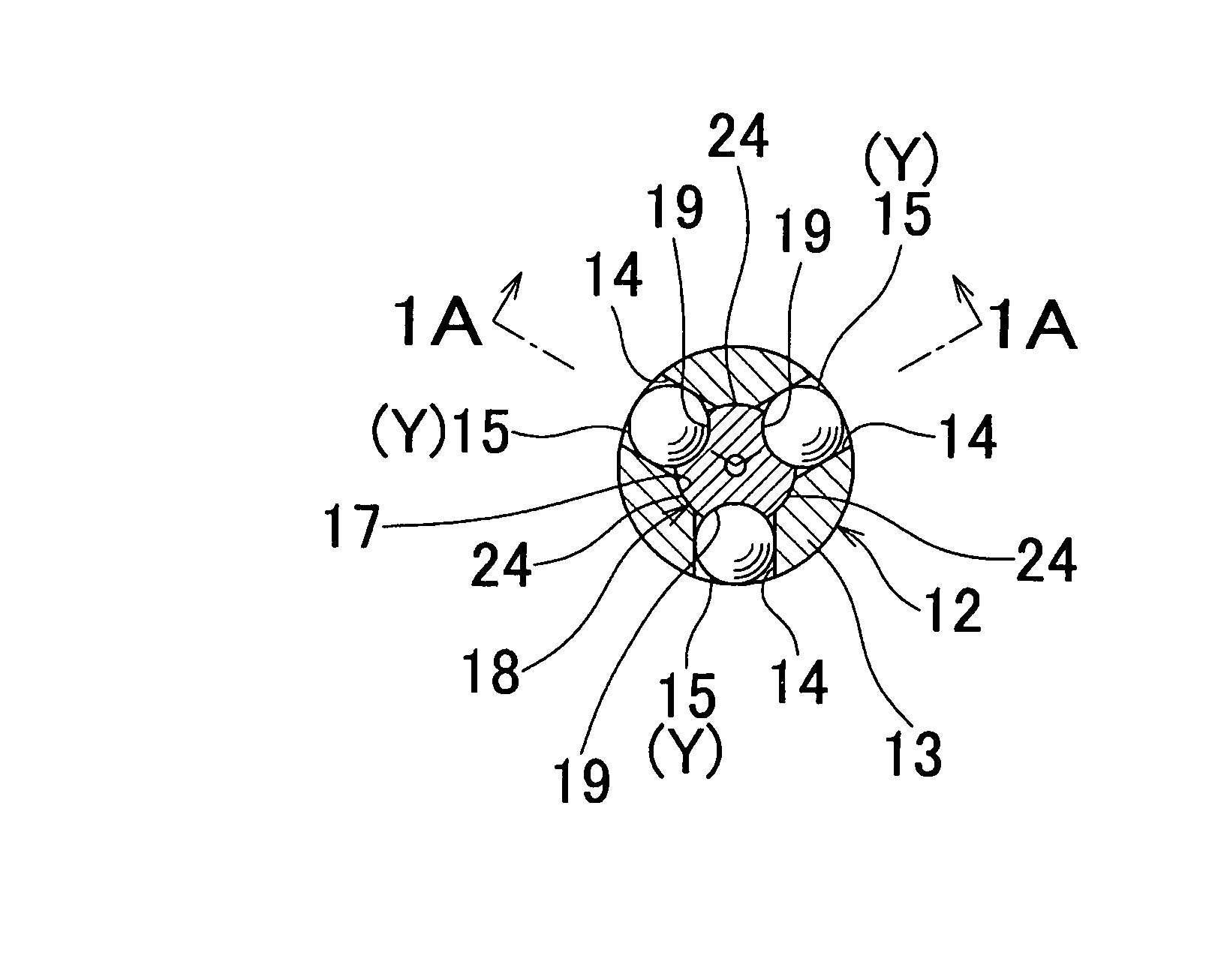
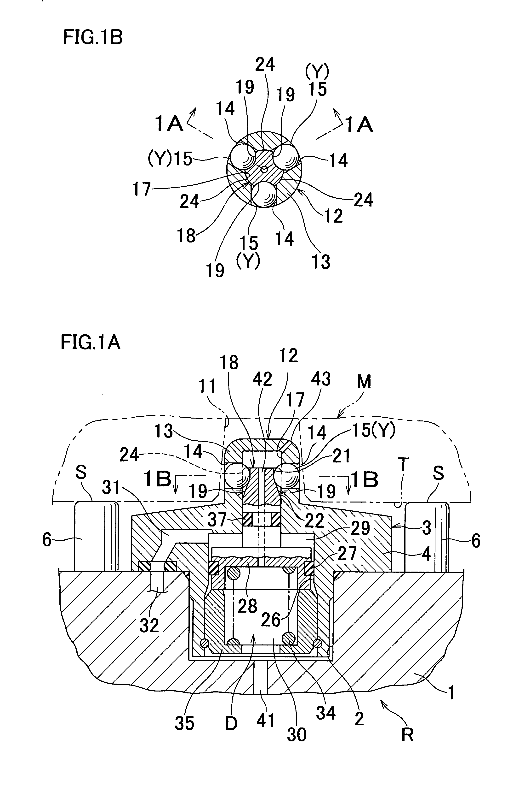
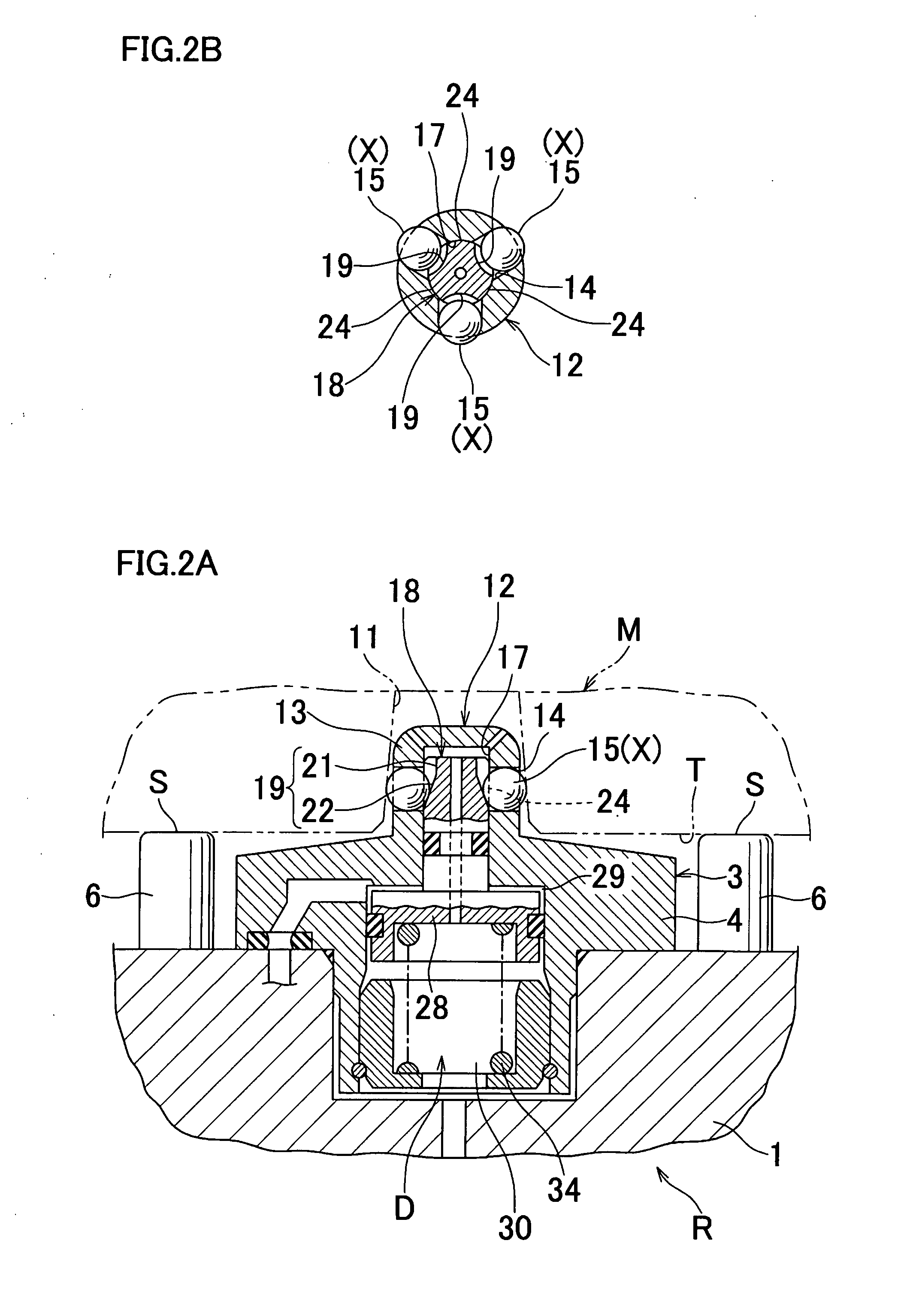
[0028]FIG. 1A is an elevational sectional view of a release state of a positioning apparatus, corresponding to a view indicated by the arrow 1A-1A of FIG. 1B. FIG. 1B is a view indicated by the arrow 1B-1B of FIG. 1A. FIG. 2A is a view similar to FIG. 1A, showing a lock state of the positioning apparatus. FIG. 2B is a view similar to FIG. 1B.

[0029] A reference member R has a work pallet 1, and a lower half of a housing 3 is fitted into an installation hole 2 of the work pallet 1. A flange portion 4 of the housing 3 is fixed to the work pallet 1 by a plurality of bolts (not shown). A plurality of columnar bosses 6 are fixed onto an upper surface of the work pallet 1, and by each support surface S provided on an upper surface of the boss 6, a supported surface T of a work M as a movable member is received.

[0030] In the work M, a cast hole 11 as an operated hole is ...


PUM


Abstract

An annular plug (12) to be inserted into a cast hole (11) of a work (M) is projected upward from a housing (3). In a peripheral wall (13) of the annular plug (12), through holes (14) extending radially are formed at intervals circumferentially. A ball (15) is inserted into each of the through holes (14). An operating rod (18) is inserted into a cylindrical hole (17) of the annular plug (12). In an outer peripheral surface of an upper end portion of the operating rod (18), accommodating grooves (19) extending vertically are formed at intervals circumferentially corresponding to the balls (15). Guide surfaces (24, 24, 24) are formed between the adjacent accommodating grooves (19, 19). These guide surfaces (24) are fitted into the cylindrical hole (17) so as to be prevented from moving radially and allowed to move axially.

Description

TECHNICAL FIELD [0001] The present invention relates to a positioning apparatus for positioning a movable member such as a work with respect to a reference member such as a work pallet and a positioning system having the same. BACKGROUND OF THE INVENTION [0002] As such a type of apparatus, one described in Patent Document 1 (Japanese Unexamined Patent Publication No. 7-314270) is conventionally available. This prior art relates to a positioning apparatus with a clamping function constructed as follows. [0003] A taper bush is attached to a lower surface of a work pallet as a movable member. A cylindrical taper pin which is fitted into a female taper hole of the taper bush is projected upward from a housing of a reference member. An operating rod is inserted into a cylindrical hole of the taper pin, and a taper pressing surface is formed on an upper part of the operating rod. The taper bush is fitted to the taper pin, thereafter, the taper pressing surface of the operating rod presses...

Claims


Application Information

Patent Timeline
IPC IPC(8): B23Q3/00
CPCB23Q1/009
Inventor HARUNA, YOSUKE
Owner KOSMEK LTD (JP)
Why Eureka
Try Eureka