
Method and System for Perpendicular Magnetic Media Metrology

a technology of magnetic media and metrology, applied in the field of metals, can solve the problems of inability to use flying spt head on a spin stand, inability to measure the magnetic properties of recording media, and the superparamagnetic limit is beginning to limit the capacity of this kind of recording

Inactive Publication Date: 2007-11-15
MICROSENSE
View PDF53 Cites 9 Cited by
  • Summary
  • Abstract
  • Description
  • Claims
  • Application Information

AI Technical Summary

Benefits of technology

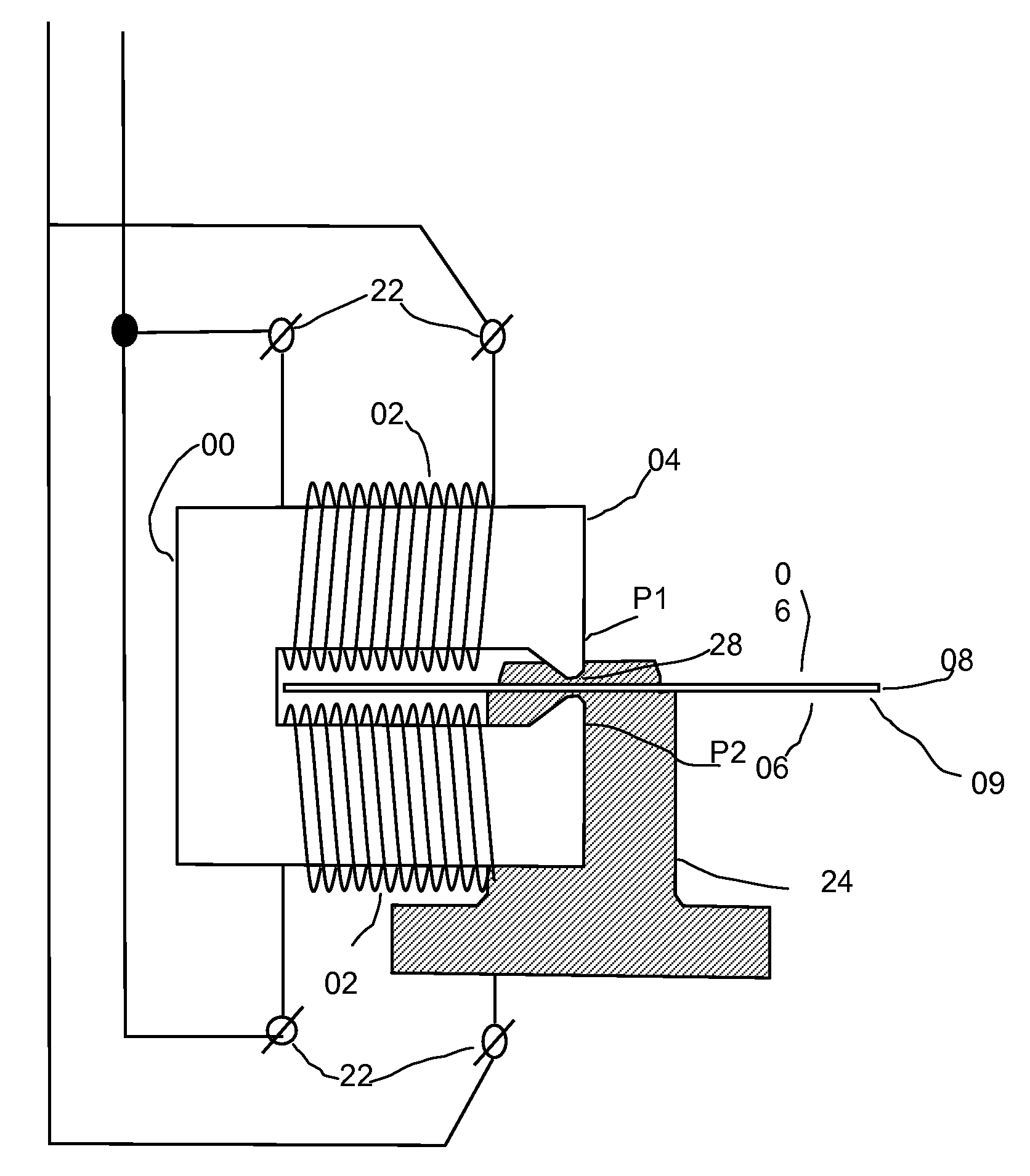
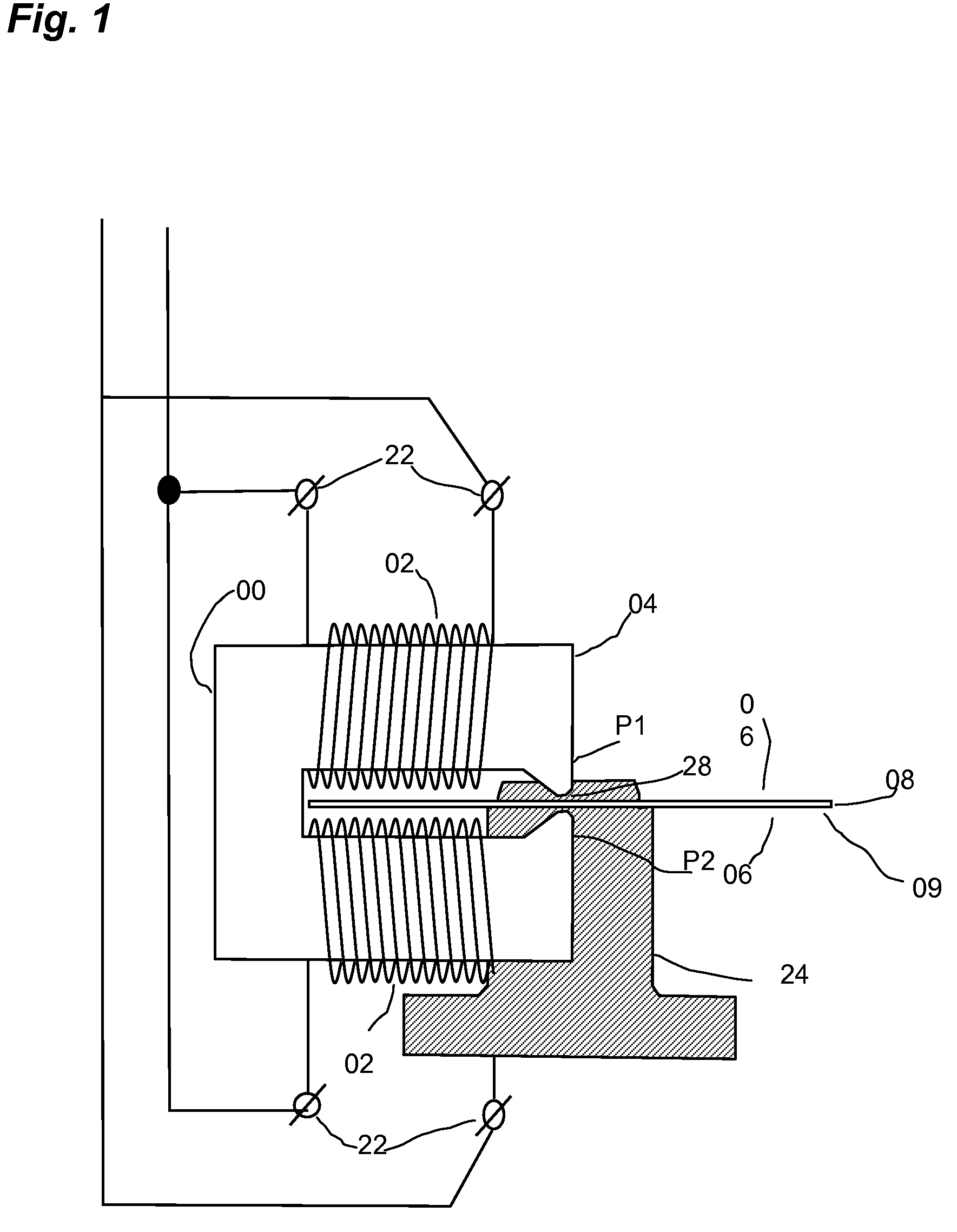
[0010]In an embodiment shown in FIG. 1, an encompassing macroscopic recording head 04, capable of generating perpendicular fields of sufficient magnitude to magnetize a perpendicularly magnetizable recording layer on a surface used for magnetic data storage is shown. The encompassing macroscopic recording head 04 is comprised of a yoke 00 and one or more coils 02. The yoke 00 is situated in such a way that one magnetic pole P1 is located on one side of the magnetic recording medium 06 on substrate

Problems solved by technology

Although increases in areal densities of nearly 100 percent every year or two for the last several years have been achieved with longitudinal techniques, it is believed that the superparamagnetic limit is beginning to limit the capacities of this kind of recording.
However, at the same time, this means that many of the conventional methods of measuring the magnetic properties of recording media may be inadequate for perpendicular recording applications, as they may not have sufficient magnetic field strength to switch the higher coercivity media.
For disk testers in line with production machines, a flying SPT head on a spin stand is not practical.
Without the flux feedback through the SUL, the perpendicular magnetic field strength of a macroscopic perpendicular SPT head is limited, and may not be enough to even write the perpendicular media.
However for perpendicular testing and inspection equipment this approach yields insufficient magnetic field perpendicular to the disk.

Method used


Image

  • Method and System for Perpendicular Magnetic Media Metrology
  • Method and System for Perpendicular Magnetic Media Metrology
  • Method and System for Perpendicular Magnetic Media Metrology

Examples


Embodiment Construction

[0036]As seen in FIG. 1, the present invention comprises an encompassing macroscopic recording head 04, having a yoke 00, and one or more coils 02. Each coil 02 has electrical connections 22 to a coil driver for generating magnetic fields. In the embodiment shown in FIG. 1, the magnetic medium is a hard drive disk platter, here device 09, having magnetic recording medium layers 06 on its top and bottom surfaces, although it should be noted that some devices 09 do not have recording layers on both sides. Typically the recording medium is a magnetic thin film layer deposited over a substrate 08 with a soft underlayer SUL 12. All perpendicular media have SULs 12. However, some perpendicular hard disk drive devices 09 have a substrate 08 comprised of aluminum and some have a substrate 08 made of glass. The present invention can also be used to measure the magnetic properties of other perpendicular media, such as magnetic tapes or cards.

[0037]In the embodiment shown in FIG. 1, device 09 ...


PUM


Abstract

A metrology system for measuring the magnetic properties of a magnetic recording medium layer on a device used for perpendicular recording.

Description

RELATED APPLICATIONS[0001]This application is a continuation of U.S. patent application Ser. No. 11 / 432,730 filed May 11, 2006, by William Van Drent, entitled Method and System for Perpendicular Magnetic Media Metrology, the disclosure of which is incorporated herein by reference in its entirety.TECHNICAL FIELD[0002]The present invention relates generally to the field of metrology and more particularly to the field of a metrology system for magnetic media used for perpendicular recording.BACKGROUND[0003]Previously, in magnetic recording technology, increasingly higher data densities have been stored on disk drives using what is known as longitudinal recording techniques. As seen in FIG. 3 (Prior Art), in longitudinal recording the magnetization on the recording medium is switched between lying parallel and anti-parallel to the direction in which the write head is moving in relation to the surface. Although increases in areal densities of nearly 100 percent every year or two for the ...

Claims


Application Information

Patent Timeline
IPC IPC(8): G01R33/12G11B5/52
CPCG01R33/12
Inventor VAN DRENT, WILLIAMVAJDA, FERENC
Owner MICROSENSE
Learn More