RFID coupler for metallic implements

Active Publication Date: 2007-11-15
ASSA ABLOY AB
View PDF41 Cites 171 Cited by
  • Summary
  • Abstract
  • Description
  • Claims
  • Application Information

AI Technical Summary

Benefits of technology

[0011] An advantage of the present invention is that the read/write distance between the reader and the RFID transponder is increased.
[0012] Another advantage is that the increased read/write distance allows better utilization

Problems solved by technology

These small “capsules” contain their own “onboard” antenna, which suffer extreme radio frequency degradation due to interference created by the proximity of the metals or liquids utilized in surgical tools implantable devices and surgical processes.
This “virtual” contact requirement makes communication with a surgically implanted

Method used


Image

  • RFID coupler for metallic implements
  • RFID coupler for metallic implements
  • RFID coupler for metallic implements

Examples


Embodiment Construction

[0020] Referring now to the drawings, and more particularly to FIGS. 2 and 3, there is shown an embodiment of an RFID tagged implement assembly 10 of the present invention, including a metallic implement 12 and an RFID transponder 14 which is coupled with implement 12 and uses implement 12 as an antenna for wireless communications. In the embodiment shown, metallic implement 12 is in the form of an surgical implement such as an orthopaedic implant or surgical instrument, but could be in form of a different type of metallic implement in which it is desirable to affix an RFID transponders. It will be appreciated that dependent upon the type of metallic implement 12, the impedance characteristics will vary as a function of the material type and geometry of the implement.

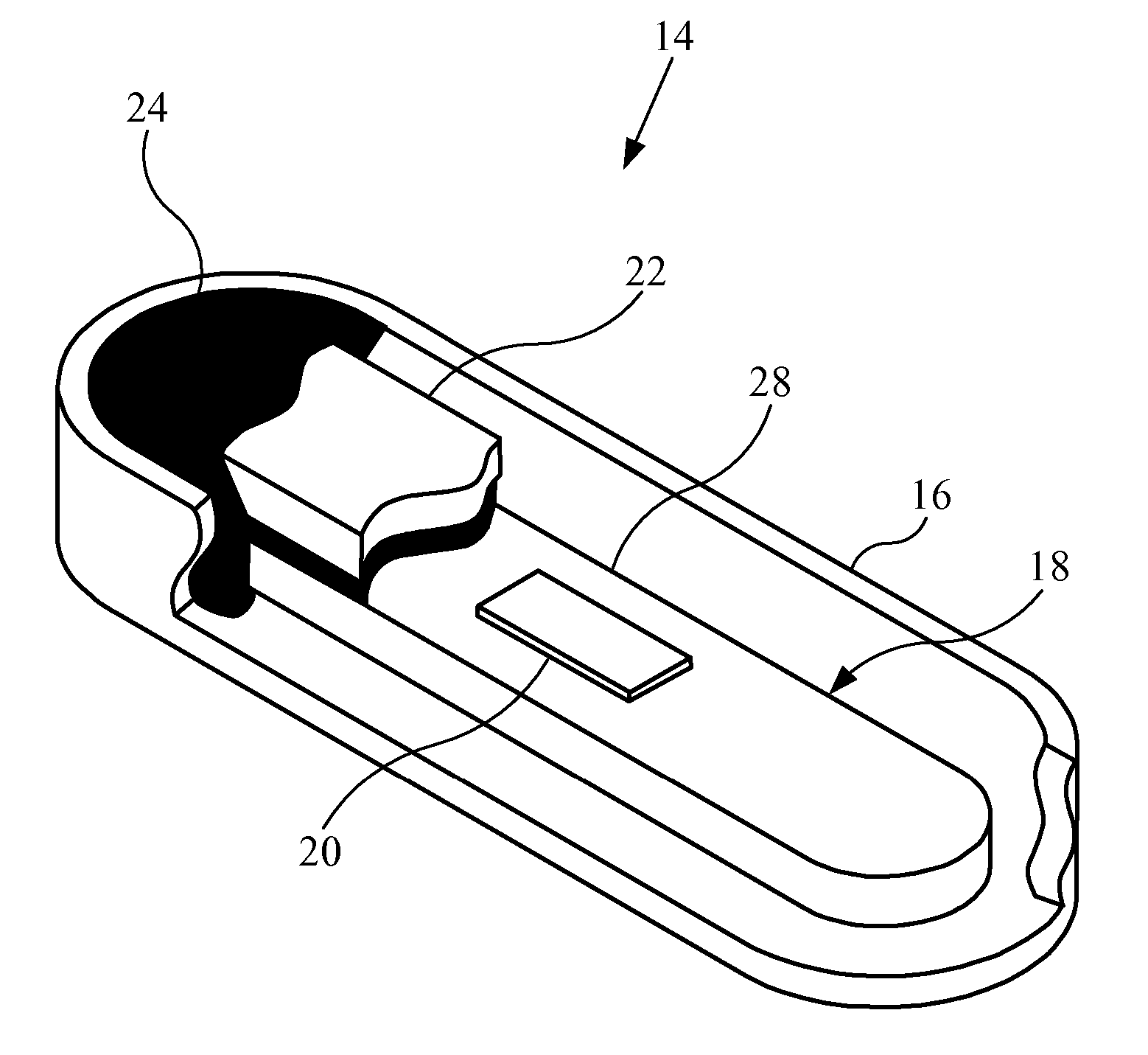
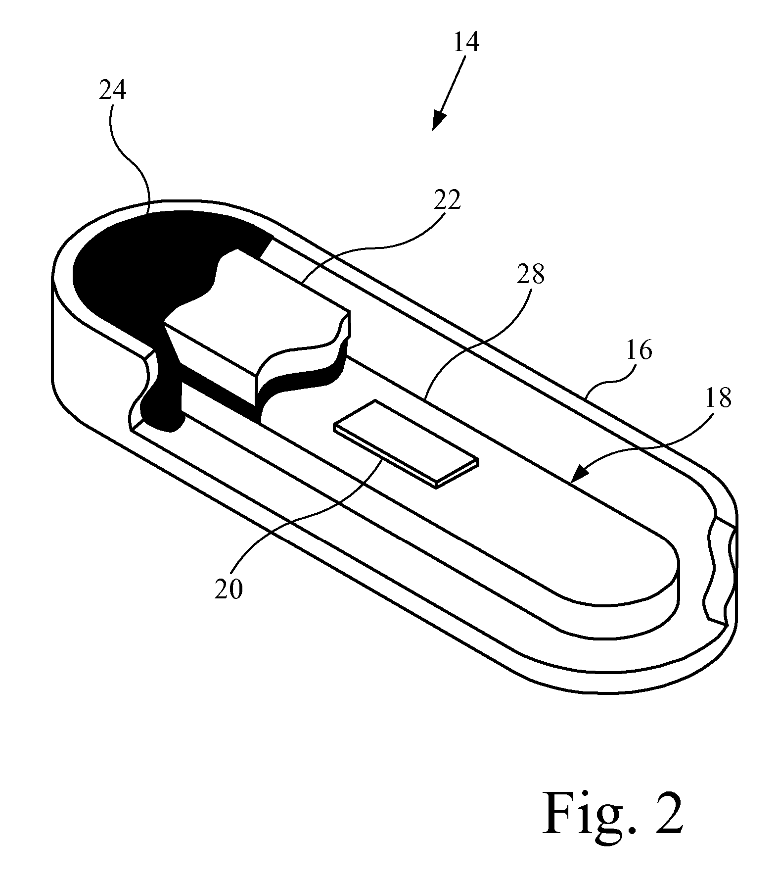
[0021] RFID transponder 14 generally includes a housing 16, inductive coupler 18 (outside of substrate 28), RFID chip 20, gamma shield 22 and potting material 24. RFID transponder 14.

[0022] Housing 16 may be of any su...


PUM


Abstract

An RFID tagged implement assembly includes a metallic implement, and a wireless RFID transponder. The RFID transponder includes a housing; an inductive coupler within the housing, and an RFID chip coupled with the inductive coupler. The inductive coupler is inductively coupled with the metallic implement.

Description

CROSS REFERENCE TO RELATED APPLICATIONS [0001] This is a non-provisional application based upon U.S. provisional patent application Ser. No. 60 / 800,090, entitled “RF TUNED IMPLANTABLE DEVICE / SURGICAL TOOL TRANSPONDER”, filed May 12, 2006.BACKGROUND OF THE INVENTION [0002] 1. Field of the Invention [0003] The present invention relates to a passive wireless transponder. [0004] 2. Description of the Related Art [0005] Radio frequency identification (RFID) tags are well known throughout industry, and are being increasingly utilized for supply chain management, inventory management, and logistic control. These tags can be written to and read from a handheld transceiver (referred to as an RFID reader) or fixed portal. [0006] Small glass encapsulated low frequency RFID tags (see FIG. 1) are currently being utilized in surgical tools and implantable devices. These small “capsules” contain their own “onboard” antenna, which suffer extreme radio frequency degradation due to interference creat...

Claims


Application Information

Patent Timeline
IPC IPC(8): G08B13/14
CPCG06K19/07749G06K19/07771G06K19/07756
Inventor WESTRICK, MICHAEL D.SANDS, DANIEL L.
Owner ASSA ABLOY AB
Why Eureka
Try Eureka