Finger-worn input device and input method applying the same

a technology of input device and finger, applied in the field of input device, can solve the problems of user's finger feeling uncomfortable and finger's way, and achieve the effect of improving user convenience and easy control of the computer cursor

Inactive Publication Date: 2007-11-15
KYE SYST CORP
View PDF7 Cites 39 Cited by
  • Summary
  • Abstract
  • Description
  • Claims
  • Application Information

AI Technical Summary

Benefits of technology

[0008] Therefore, it is an objective of the present invention to provide a finger-worn input device and an input method applying the same, in which the movement detecting unit and the main controller are disposed separately. With such device, the users can easily control the computer cursor on any surface without having to grab the input pointing device while typing on the keyboard, so as to improve the user convenience.

Problems solved by technology

The patents mentioned above have the following disadvantages: (1) While it is being used, the users have to insert their finger into the finger stall, and after long usage, the user's finger will feel uncomfortable; (2) in the U.S. Pat. No. 5,706,026, the controller unit is worn on the user's wrist and the finger stall is connected to the controller unit through an electric wire, but the electric wire will most likely block the finger's way.

Method used


Image

  • Finger-worn input device and input method applying the same
  • Finger-worn input device and input method applying the same
  • Finger-worn input device and input method applying the same

Examples


Embodiment Construction

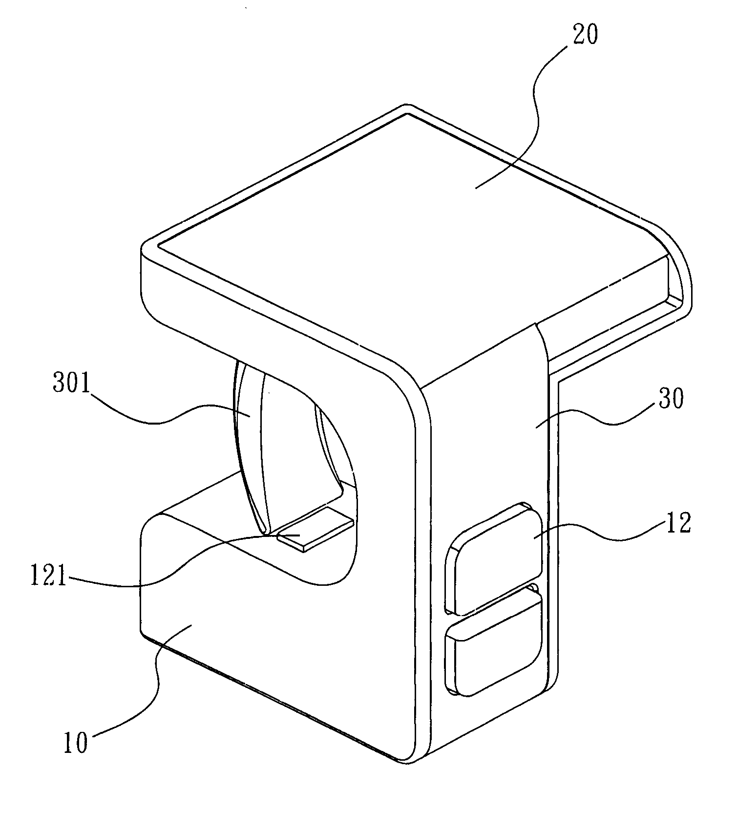
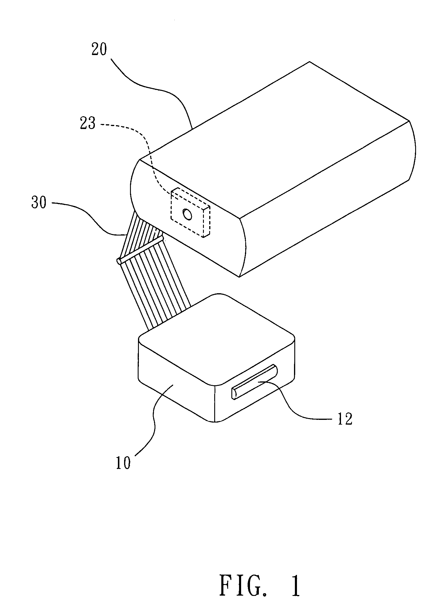
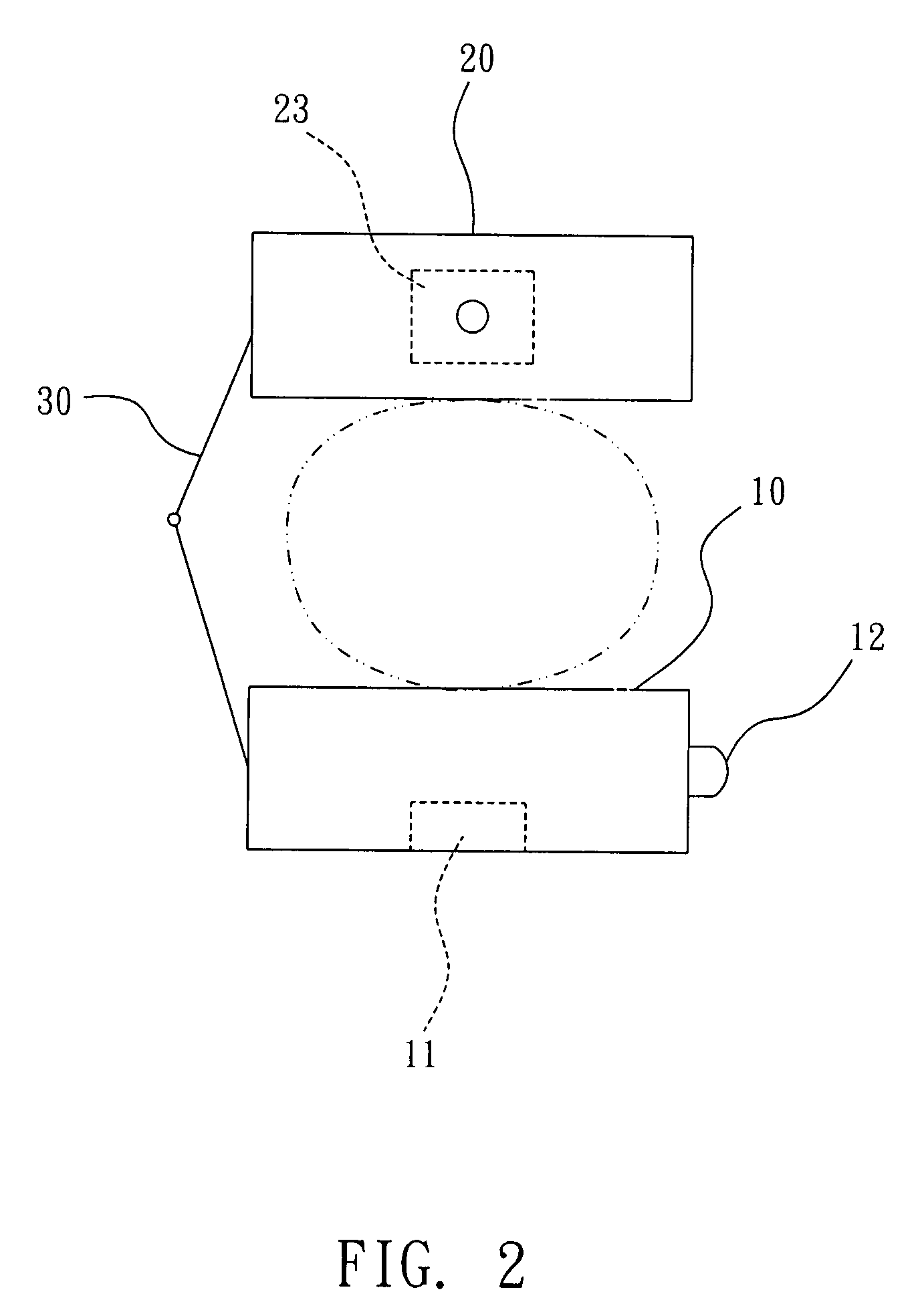
[0023] Referring to FIGS. 1 and 2, wherein FIG. 1 is a schematic composition diagram of a finger-worn input device according to a preferred embodiment of the present invention, and FIG. 2 is a schematic diagram showing the usage of the finger-worn input device provided by the present invention. As shown in FIG. 1, the finger-worn input device of the present invention comprises a movement detecting unit 10; a main controller 20; and a connection structure 30.

[0024] A movement detector 11 and at least a key 12 are configured on the movement detecting unit 10. Wherein, the movement detector 11 is disposed on the bottom of the movement detecting unit 10 to detect a movement signal, and the key 12 is disposed in the inner or outer side of the movement detecting unit 10, for example but not limited, it is on the right side or the inner side when the user's finger is inserted therein. While it is triggered, the key 12 will generate a key signal.

[0025] The main controller 20 is disposed a...


PUM


Abstract

The present invention relates to a finger-worn input device, which comprises a movement detecting unit, a main controller and a connection structure. After being assembled, users can insert their finger in between the movement detecting unit and the main controller in order to move the movement detecting unit and to press a key. The main controller receives a movement signal and a key signal, converts these signals into a computer control signal, which is then transmitted to a computer for further process through a wired or wireless transmission method. By using the finger-worn input device with the structure mentioned above, the user usage is more convenient and the input device can be minimized. In addition, the present invention also discloses an input method applying the finger-worn input device.

Description

BACKGROUND OF THE INVENTION [0001] 1. Field of the Invention [0002] The present invention relates to an input device, and more particularly, to a finger-worn input device for the users that are using the computer mouse / input device to control the computer cursor on any surface without having to grab the input pointing device while typing on the keyboard, so as to improve the user convenience, and an input method applying the finger-worn input device. [0003] 2. Description of the Related Art [0004] The computer mouse / input device of the current market usually configures a movement detecting unit and a controller inside its main body. While being used, the computer mouse / input device is moved by the user to a desired position and a button located thereon is pressed down, such that the controller can transmit a movement movement to a computer for further process. [0005] Regarding to the related techniques, please refer to public patent information disclosed in the approved ROC Patent N...

Claims


Application Information

Patent Timeline
Patent Type & Authority Applications(United States)
IPC IPC(8): G06F3/033
CPCG06F2203/0331G06F3/033
Inventor CAI, ZHENG-ZHECHEN, ZHEN-BANGWANG, ZHONG-NANLIN, LI-WEN
Owner KYE SYST CORP
Why Eureka
Try Eureka