Ink-jet head

a technology of inkjet head and inkjet printer, which is applied in the direction of printing and inking apparatus, etc., can solve the problems of excessive temperature rise the inability to quickly remove the heat generated in etc., and achieve the effect of hardly excessively increasing the temperature of the driver ic chip

Active Publication Date: 2007-11-15
BROTHER KOGYO KK
View PDF1 Cites 20 Cited by
  • Summary
  • Abstract
  • Description
  • Claims
  • Application Information

AI Technical Summary

Benefits of technology

[0008]According to the aspect, heat generated in the driver IC chip is not only transferred through the first heat-transfer member to the heat sink that makes the outer surface of the head and then released from the heat sink to the outside of the head, but also released through the first and second heat-transfer members to the metal portion of the head main body. Therefore, even when the heat sink is small in size, a temperature of the driver IC chip is hardly excessively increased.

Problems solved by technology

Therefore, if the heat sink is downsized, a surface area of the heat sink decreases so that heat generated in the driver IC chip cannot be quickly removed from the driver IC chip.
This may cause an excessive temperature rise in the driver IC chip.

Method used


Image

  • Ink-jet head
  • Ink-jet head
  • Ink-jet head

Examples


Embodiment Construction

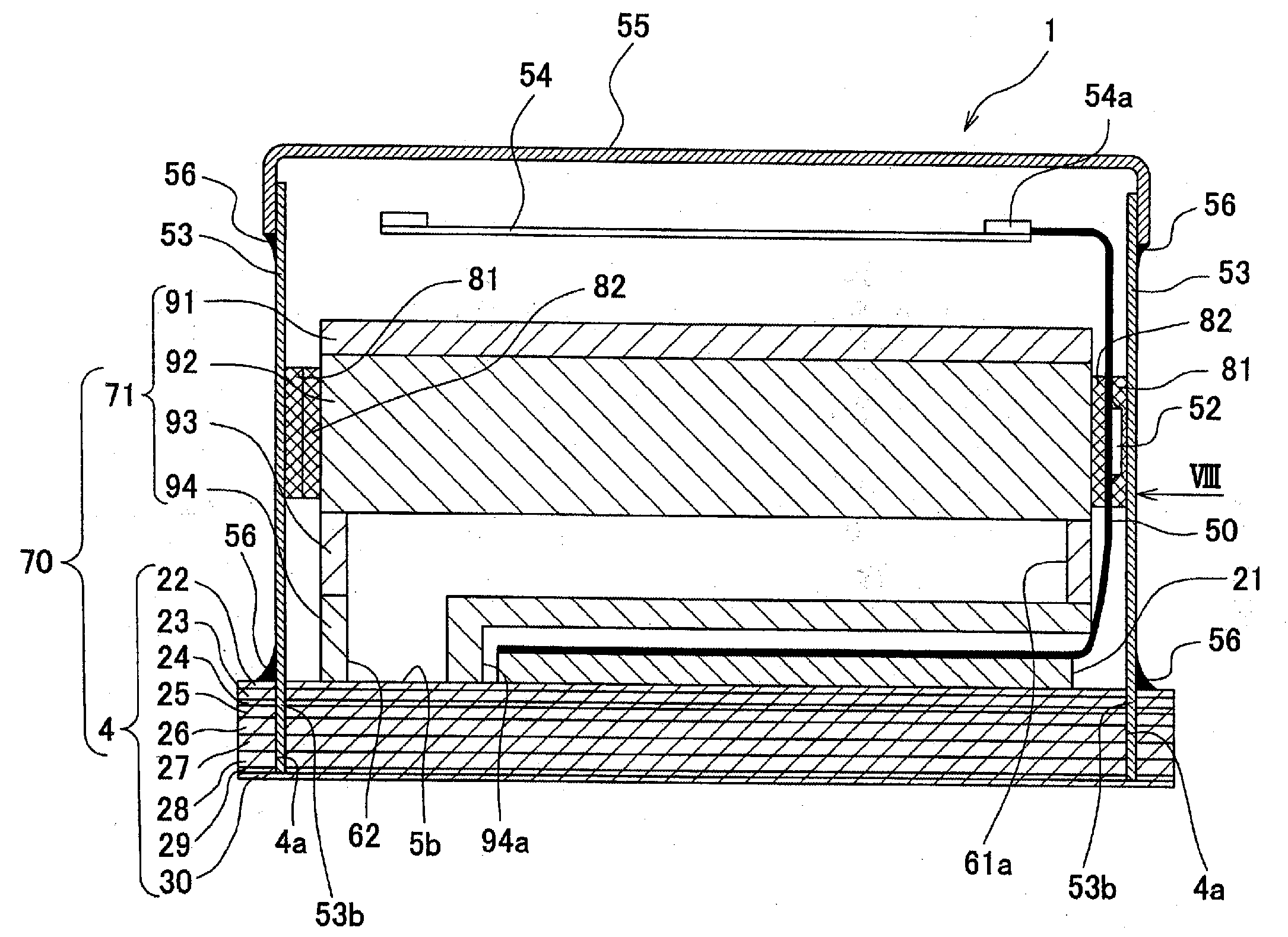
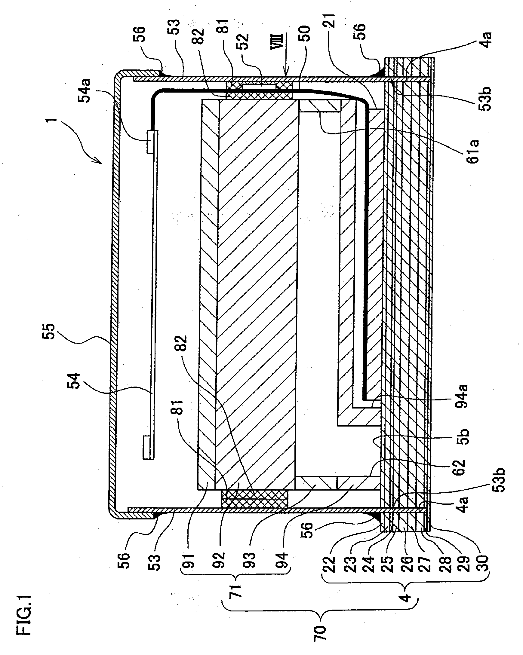
[0025]An ink-jet head 1 shown in FIG. 1 is, in a functional sense, made up mainly of three components, namely, a head main body 70, a head driver, and a protective casing. The ink-jet head 1 has a rectangular parallelepiped shape elongated in one direction.

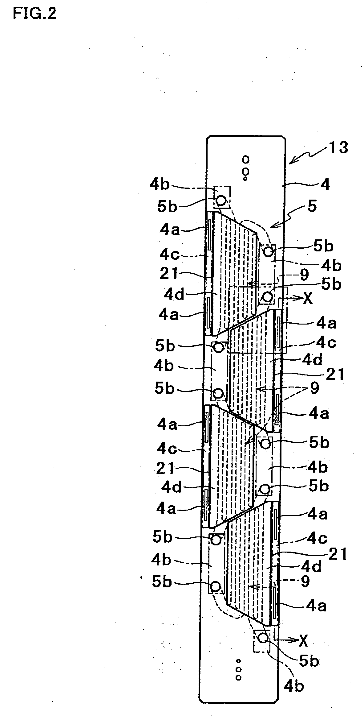
[0026]The head main body 70 includes a passage unit 4 and a reservoir unit 71. Ink passages are formed inside the head main body 70. The ink passages are involved in temporarily storing, distributing, and ejecting ink that has been supplied from the outside. Ink is ejected from nozzles formed in the passage unit 4, thus forming an image is formed on a record medium. The head driver includes a piezoelectric actuator 21, a substrate 54 having various electronic components mounted thereon, and a Chip On Film (COF) 50 which is a flexible power supply member and electrically connects the piezoelectric actuator 21 and the substrate 54 to each other. A driver IC chip 52 that drives the piezoelectric actuator 21 is mounted on a surface of...


PUM


Abstract

An ink-jet head includes a head main body having a metal portion, an actuator, a power supply member, and a heat sink that makes an outer surface of the ink-jet head. The power supply member includes a base, and a driver IC chip that is mounted on the base and drives the actuator. A first heat-transfer member is positioned between the driver IC chip and the heat sink. A second heat-transfer member is positioned between the base and the metal portion. The first heat-transfer member is in contact with the second heat-transfer member without interposition of the base.

Description

BACKGROUND OF THE INVENTION[0001]1. Field of the Invention[0002]The present invention relates to an ink-jet head that ejects ink from a nozzle.[0003]2. Description of the Related Art[0004]An ink-jet head that ejects an ink droplet from a nozzle is sometimes provided with a heat sink that absorbs heat generated in a driver IC chip and releases the heat to outside of the head in order to avoid excessive temperature rise in the driver IC chip that drives an actuator for applying ejection energy to ink. In a recording head disclosed in Japanese Unexamined Patent Publication No. 2005-178306, a flexible wire cable having an IC chip mounted thereon is disposed on an upper face of a piezoelectric actuator, and a surface of the IC chip is in contact with a side wall of a heat sink. Accordingly, heat generated in the IC chip is transmitted to the heat sink and then released from the heat sink to outside of the head.SUMMARY OF THE INVENTION[0005]In order to downsize the recording head disclose...

Claims


Application Information

Patent Timeline
Patent Type & Authority Applications(United States)
IPC IPC(8): B41J2/04
CPCB41J2/14209B41J2002/14217B41J2002/14225B41J2002/14306B41J2202/20B41J2002/14459B41J2002/14491B41J2202/08B41J2002/14419
Inventor ITO, KOJI
Owner BROTHER KOGYO KK
Why Eureka
Try Eureka