

Liquid container, head cartridge, ink jet printing apparatus, and stirring method for liquid container
a technology of ink jet printing and liquid container, which is applied in the directions of printing, transportation and packaging, mixing, etc., can solve the problems of unnecessarily high density image printing, low light resistance and gas resistance of dye ink, and low durability of matter with dye ink, so as to achieve efficient stirring, reduce the concentration gradient of liquid, and easy and reliably raised
- Summary
- Abstract
- Description
- Claims
- Application Information
AI Technical Summary
Benefits of technology
Problems solved by technology
Method used
Image

Examples
first embodiment
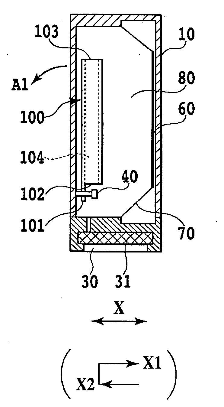
[0101]A liquid container of this embodiment is an ink tank that is mountable on a so-called serial scan type ink jet printing apparatus.
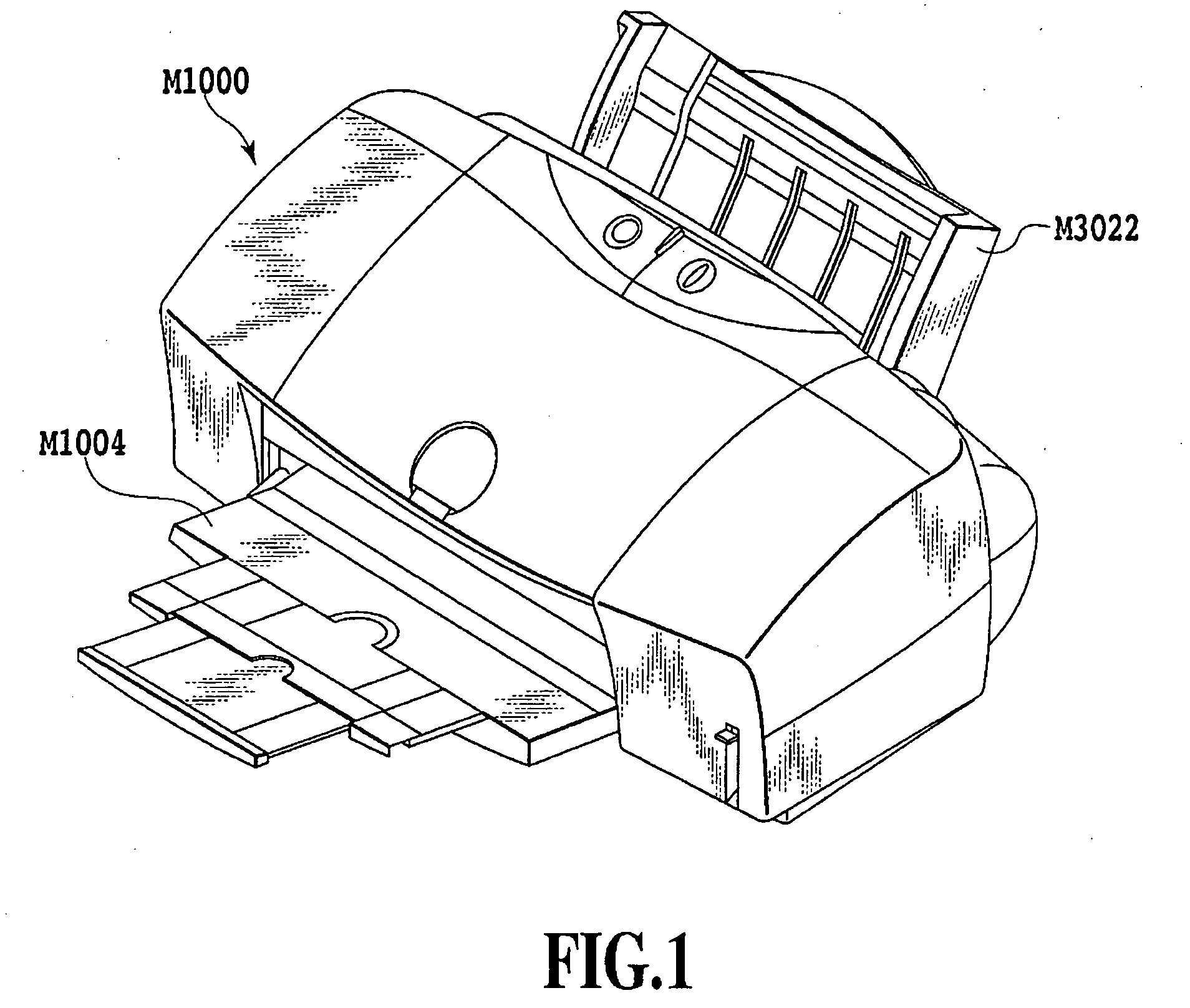
[0102]FIG. 1 is an exterior perspective view of an, ink jet printing apparatus in this embodiment. The printing apparatus primarily includes an apparatus main body M1000 that performs printing on a printing medium, a feed unit M3022 that supplies the printing medium into the apparatus, and a discharge tray M1004 that receives the printing medium after printing.
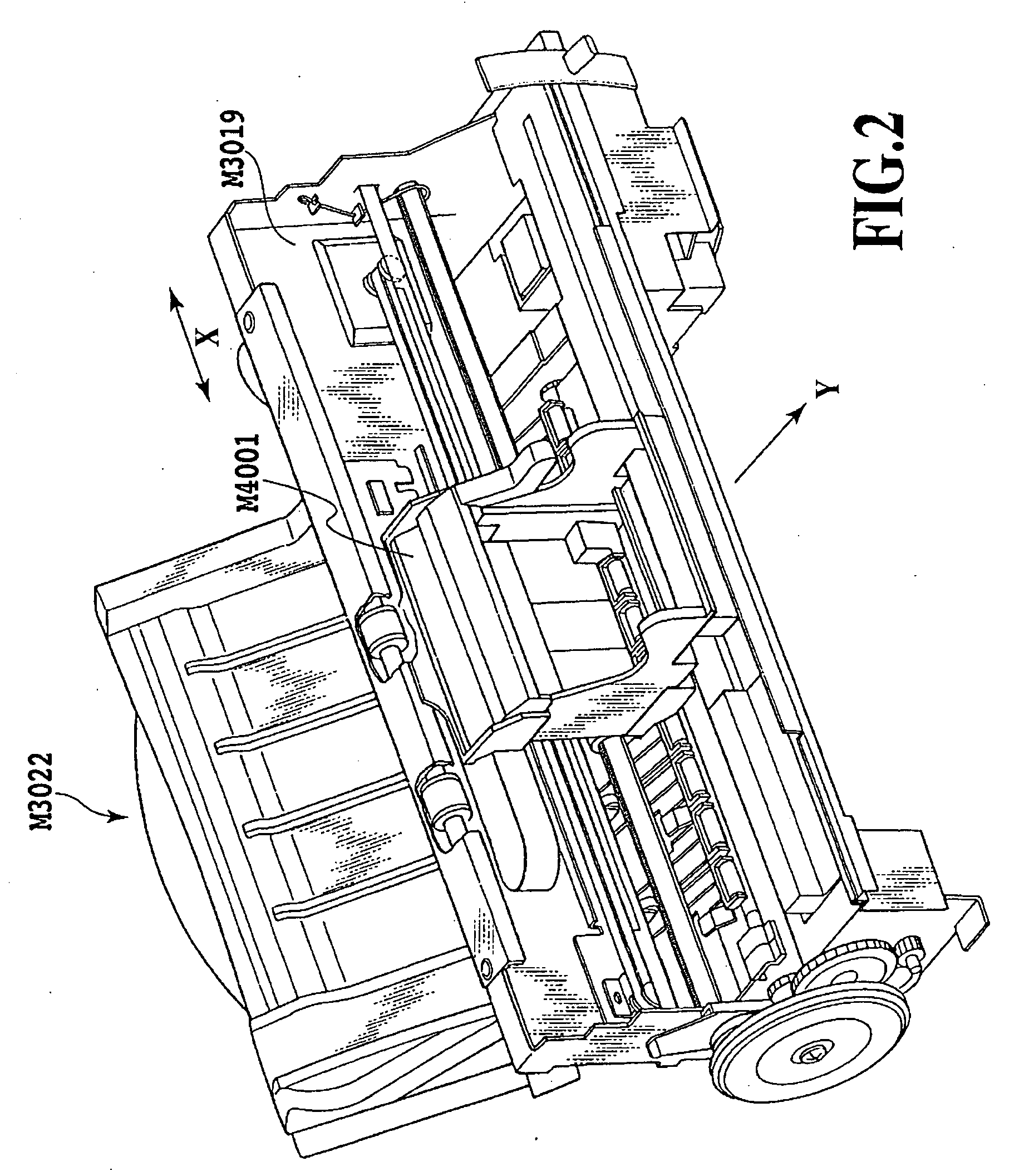
[0103]FIG. 2 is a perspective view illustrating the internal configuration of the apparatus main body M1000. Main internal mechanisms of the apparatus main body M1000 are installed and protected in a chassis M3019. Reference numeral M4001 denotes a carriage that can reciprocate in a main scanning direction of an arrow X while a printing head cartridge (not shown) is mounted thereon. The printing head cartridge has an ink jet printing head, as described below. If a printing operation command is...
second embodiment
[0152]Next, a second embodiment of the present invention will be described. In this embodiment, the liquid container is an ink cartridge that is mountable on the above-described printing apparatus shown in FIGS. 1 to 3. In the ink tank of this embodiment, the volume of the ink containing chamber is not decreased even though ink is consumed. That is, the volume of the ink containing chamber is not decreased, but only the amount of ink in the ink containing chamber is decreased.
(Overall Configuration of Ink Tank)
[0153]FIG. 17 is an exploded perspective view of an ink tank 2 of this embodiment. The ink tank 2 is a container that has an ink containing chamber 180 therein. The ink tank 2 primarily includes an ink container case body 110 and a cover member 120. An ink supply port 130 is formed at the bottom of the ink tank 2 to supply ink to the printing head. Further, an atmosphere communicating port 110A is formed at the top of the ink tank 2. In the ink tank 2, when the ink containing ...
third embodiment
[0166]Next, a third embodiment of the present invention will be described.
[0167]In this embodiment, as shown in FIG. 23, in an ink jet printing apparatus M1001, a printing head cartridge H1002 is detachably mounted on a carriage M4001 that can reciprocate in the main scanning direction (the direction of the arrow X) along a shaft M4002. The printing head cartridge H1002 has the configuration in which a sub tank (liquid container) 3 and a printing head H1000 are formed as a single body. As shown in FIG. 24, similarly to the ink tank 1 of the second embodiment described above, a swing member 300 is provided in the sub tank 3. Ink 90 in the sub tank 3 is supplied to a printing chip forming the printing head H1000 through a filter 1303 and an ink flow passage 1304 and ejected from an ejection port of the printing head H1000.
[0168]A tube 1301 is connected between the sub tank 3 and a main tank 1311 that is provided outside the carriage M4001. Ink 90 is contained in the main tank 1311, an...
PUM
| Property | Measurement | Unit |
|---|---|---|
| permeation size | aaaaa | aaaaa |
| thickness | aaaaa | aaaaa |
| swing angle | aaaaa | aaaaa |
Abstract
Description
Claims
Application Information