Bicycle sprocket

a technology for bicycles and sprockets, which is applied in the direction of mechanical equipment, transportation and packaging, hoisting equipment, etc., can solve the problems of non-metallic inner ring deterioration

Inactive Publication Date: 2007-11-15
SHIMANO INC
View PDF31 Cites 86 Cited by
  • Summary
  • Abstract
  • Description
  • Claims
  • Application Information

AI Technical Summary

Benefits of technology

[0012]One object of the present invention is to provide a bicyc...

Problems solved by technology

Although the bicycle sprockets having a metallic sprocket ring part and a non-metallic inner ring part have proven to be very advantageous in saving weight while still providing sufficient stiffness ...

Method used


Image

  • Bicycle sprocket
  • Bicycle sprocket
  • Bicycle sprocket

Examples


Embodiment Construction

[0034]Selected embodiments of the present invention will now be explained with reference to the drawings. It will be apparent to those skilled in the art from this disclosure that the following descriptions of the embodiments of the present invention are provided for illustration only and not for the purpose of limiting the invention as defined by the appended claims and their equivalents.

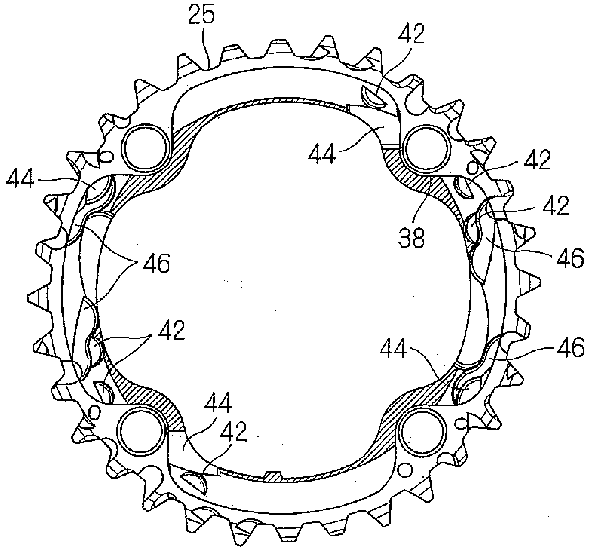
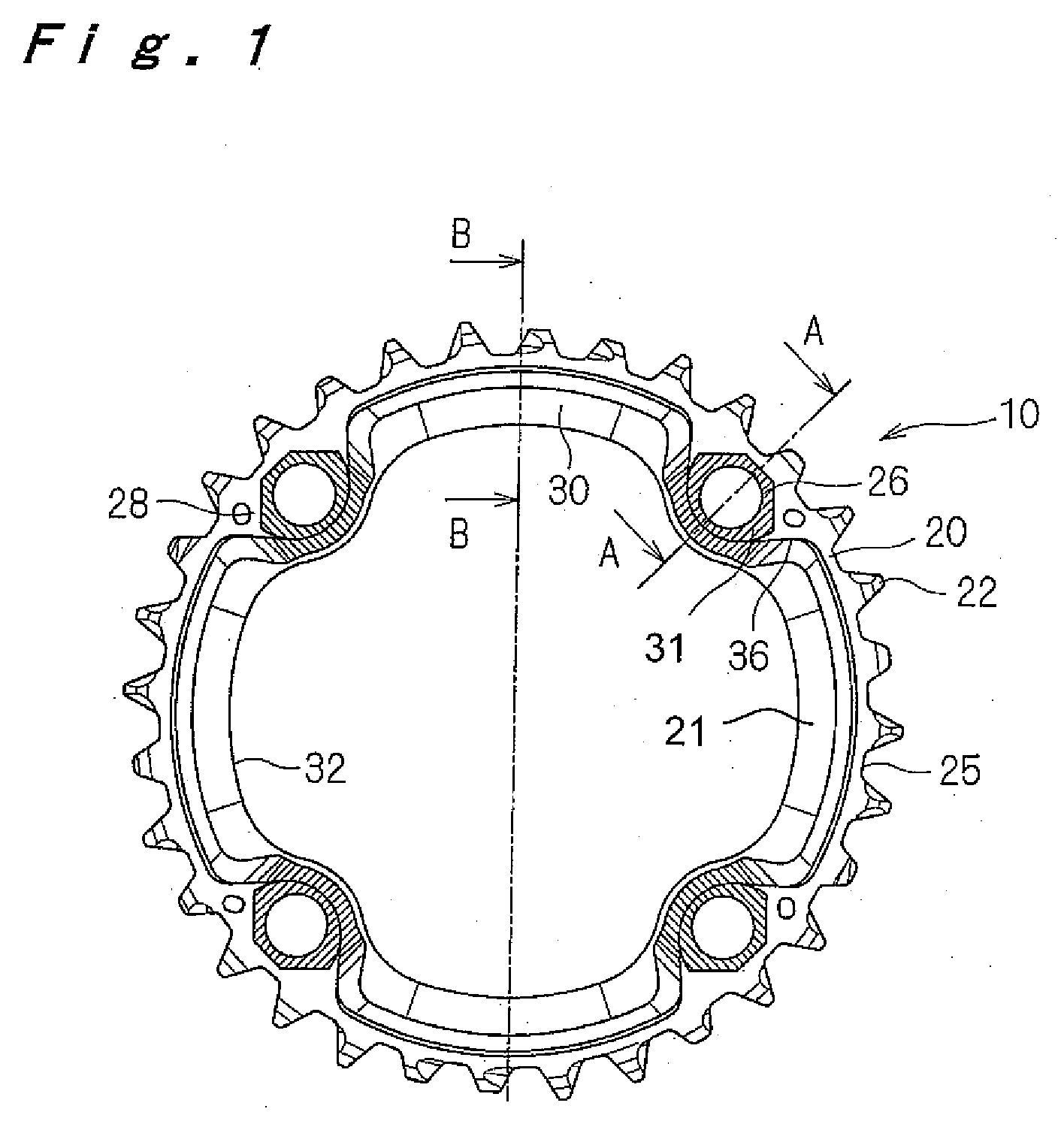
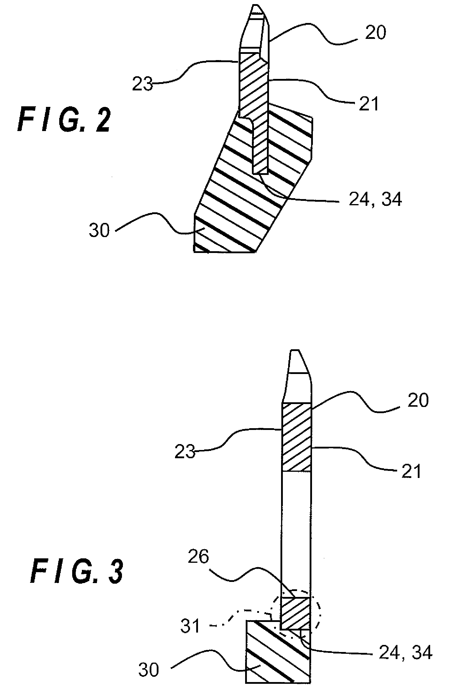
[0035]Referring initially to FIG. 1, a bicycle sprocket is illustrated in accordance with a first embodiment of the present invention. In FIG. 1 the bicycle sprocket is viewed from the outer side or side to which a crank is to be mounted. The bicycle sprocket as shown basically includes a metallic sprocket ring part 20 with a plurality of sprocket teeth 22 and a non-metallic inner ring part 30. It is to be noted that the non-metallic inner ring part 30 is represented as being uncolored for illustrative purpose whereas usually the non-metallic inner ring part 30 will be made of a synthetic resin wit...


PUM


Abstract

A bicycle sprocket is provided with a metallic sprocket ring part and a non-metallic inner ring part. The metallic sprocket ring part has a crank facing surface, an opposing surface, an inner periphery and an outer periphery with a plurality of sprocket teeth arranged thereon. The sprocket ring part includes at least one connecting portion integrally formed with the sprocket ring part as a one-piece, unitary member. The non-metallic inner ring part at least partially overlaps the inner periphery of the metallic sprocket ring part to at least partially non-movably couple the non-metallic inner ring part to the metallic sprocket ring part with at least one selected portion being absent of the non-metallic inner ring part to allow relative elastic deformation between the metallic sprocket ring part and the non-metallic inner ring in an axial direction

Description

CROSS-REFERENCE TO RELATED APPLICATIONS[0001]This application claims priority under 35 U.S.C. § 119 to German Patent Application No. 10 2006 022 343.8 filed on May 12, 2006. The entire disclosure of German Patent Application No. 10 2006 022 343.8 is hereby incorporated herein by reference.BACKGROUND OF THE INVENTION[0002]1. Field of the Invention[0003]This invention generally relates to a bicycle sprocket. More specifically, the present invention relates to a bicycle sprocket comprising a metallic element and a non-metallic element, with the bicycle sprocket being configured to be mounted to a rotational drive unit such as a crank of a bicycle.[0004]2. Background Information[0005]Bicycling is becoming an increasingly more popular form of recreation as well as a means of transportation. Moreover, bicycling has become a very popular competitive sport for both amateurs and professionals. Whether the bicycle is used for recreation, transportation or competition, the bicycle industry is ...

Claims


Application Information

Patent Timeline
IPC IPC(8): F16H55/30
CPCF16H55/30B62M9/105
Inventor EMURA, ATSUHIRONONOSHITA, TETSU
Owner SHIMANO INC
Why Eureka
Try Eureka